Incandescent halogen lamp having flattened filament support leads

a technology of filament support and incandescent halogen lamps, which is applied in the manufacture of electrode systems, cold cathode manufacturing, electric discharge tubes/lamps, etc., can solve the problems of affecting the performance of the lamp, and affecting the quality of the lamp. , to achieve the effect of reducing the amount of light reflected and reducing the rough surface textur

Inactive Publication Date: 2005-02-15
FEDERAL MOGUL WORLD WIDE
View PDF9 Cites 7 Cited by
  • Summary
  • Abstract
  • Description
  • Claims
  • Application Information

AI Technical Summary

Benefits of technology

In accordance with another aspect of the present invention, there is provided a method for of forming the incandescent lamp. The method includes the steps of forming a first lead wire by flattening an end portion of a section of electrically-conductive wire, providing a second lead wire formed from a section of electrically-conductive wire, attaching a filament between the second lead wire and the flattened end portion of the first lead wire, and sealing the filament and at least a portion of the first and second lead wires wi...

Problems solved by technology

In traditional incandescent lamps, the released tungsten atoms are deposited onto a large glass bulb surrounding the filament, thereby darkening the bulb and weakening the filament.
For instance, a portion of the total light emitted from incandescent halogen lamps often reflects off of interior components of the lamp, such as the lead wires, and results in uncontrolled stray light appearing as glare to oncoming drivers.
Halogen ...

Method used


Image

  • Incandescent halogen lamp having flattened filament support leads
  • Incandescent halogen lamp having flattened filament support leads
  • Incandescent halogen lamp having flattened filament support leads

Examples


Embodiment Construction

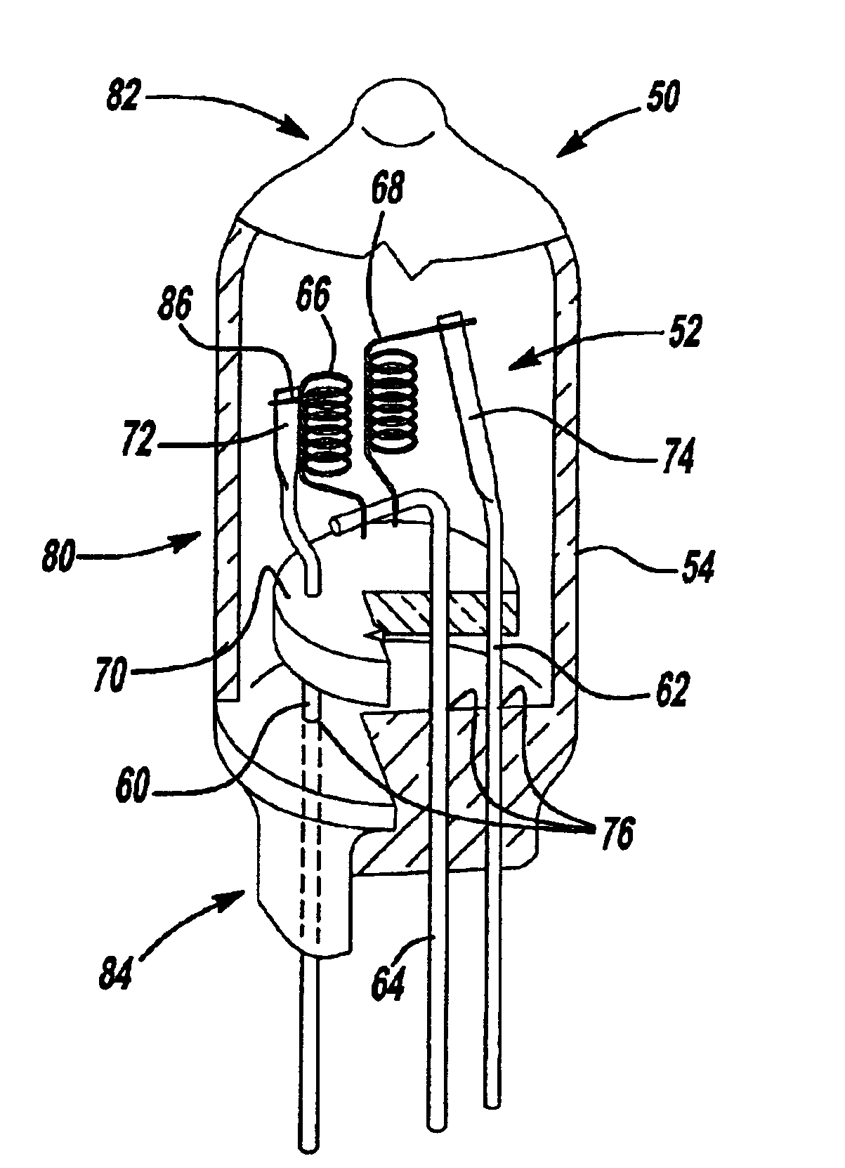
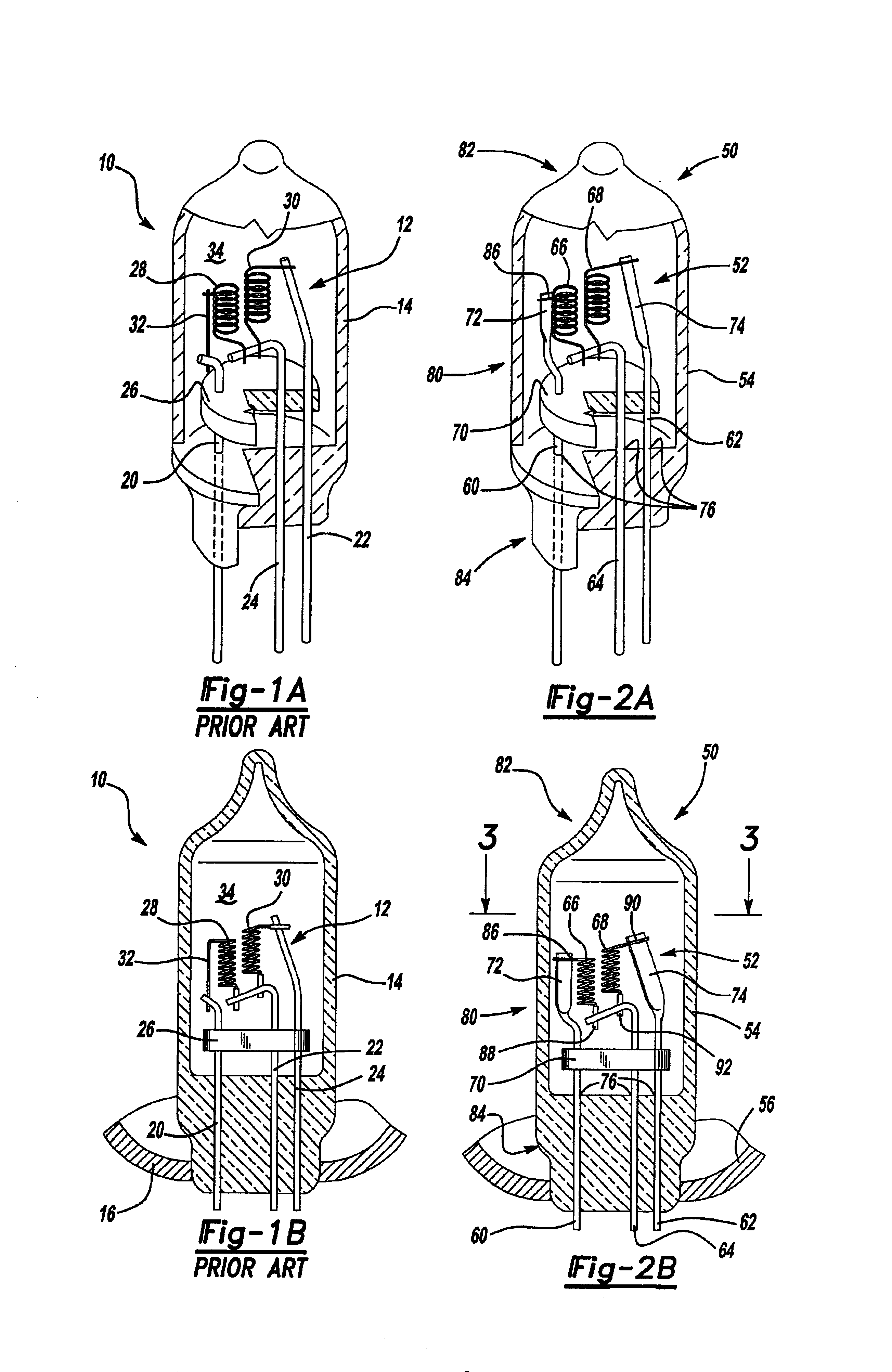
Referring to FIGS. 1A-B, there is shown a prior art incandescent halogen lamp 10 that generally includes interior components 12 and an envelope 14, and is surrounded by a parabolic reflector 16. The interior components are responsible for illumination, and are further comprised of several filament support lead wires 20, 22, and 24 that pass through a disk-like support bridge 26 and supply electric current to a high beam filament 28 and a low beam filament 30. High beam filament 28 further includes a thin leg portion 32, which extends outwardly from the filament and is bent downwards such that it continues alongside the filament until it connects with lead wire 20 at an axial position below filament 28. Envelope 14 is typically made of high temperature materials such as quartz or other suitable glass, and surrounds the interior components such that a sealed environment 34 is formed. This environment commonly consists of a combination of halogen and inert gases and is essential to the...


PUM


Abstract

An incandescent halogen lamp used in connection with a vehicle headlamp system in which stray light attributable to reflection off of internal lamp components is reduced while the structural integrity of the lamp is maintained. The halogen lamp includes two filaments, several lead wires, and a support bridge all sealed within a glass envelope. Each filament is connected at its outermost end to a flattened end portion of a lead wire which extends along the length of the filament from near the support bridge to the upper end of the filament. The flattened outer ends of the lead wires have a narrow profile that is in alignment with the direction of illumination of light from their respective filaments. This arrangement reduces the surface area that could otherwise interfere with light emitted by the filaments, and thereby reduces the overall stray light produced by the lamp. The flattened outer ends can have a roughened surface to further help reduce the amount of light reflected off the lead wires.

Description

FIELD OF THE INVENTIONThe present invention relates generally to incandescent halogen lamp assemblies, and more particularly to incandescent halogen lamp assemblies used in vehicle headlamp systems that are designed to reduce glare attributable to reflection from interior lamp components.BACKGROUND OF THE INVENTIONVehicle headlamp systems have experienced many adaptations over the years, including the use of incandescent halogen lamps which result in increased light output and lower energy consumption. Unlike traditional incandescent lamps, where a filament is surrounded by an inert gas such as argon (Ar), incandescent halogen lamps envelop the filament with a gas composition that includes a gas from the halogen group. In both designs, the filament, generally tungsten (W), is supported by and connected to electric current carrying lead wires which supply the filament with current and cause it to become a glowing “white hot” according to a process commonly known as incandescence. A c...

Claims


Application Information

Patent Timeline
IPC IPC(8): H01J9/04H01K1/00H01J9/02H01K1/50H01K1/18H01K3/08H01K3/20H01K9/00
CPCH01K1/18H01K9/00H01K3/20H01K3/08
Inventor WEYHRAUCH, ERNEST C.
Owner FEDERAL MOGUL WORLD WIDE
Why Eureka
Try Eureka