
EMI suppression method for powertrain control modules

a powertrain control module and electromagnetic compatibility technology, applied in the direction of cross-talk/noise/interference reduction, line-transmission details, waveguide type devices, etc., can solve the problems of processor electromagnetic compatibility (emc) problems, and achieve the effect of improving electrical and mechanical conta

Inactive Publication Date: 2005-02-15
MICHIGAN MOTOR TECH LLC
View PDF15 Cites 8 Cited by
  • Summary
  • Abstract
  • Description
  • Claims
  • Application Information

AI Technical Summary

Benefits of technology

In yet another aspect of the present invention the fastening means includes a barbed surface for providing improved electrical and mechanical contact.

Problems solved by technology

This design will provide some immunity to external electromagnetic interference (EMI), but may not necessarily quell radiated emissions.
Virtually all PCMs equipped with Motorola Oak processors or similar type of processor have experienced electromagnetic compatibility (EMC) issues.

Method used


Image

  • EMI suppression method for powertrain control modules
  • EMI suppression method for powertrain control modules
  • EMI suppression method for powertrain control modules

Examples


Embodiment Construction

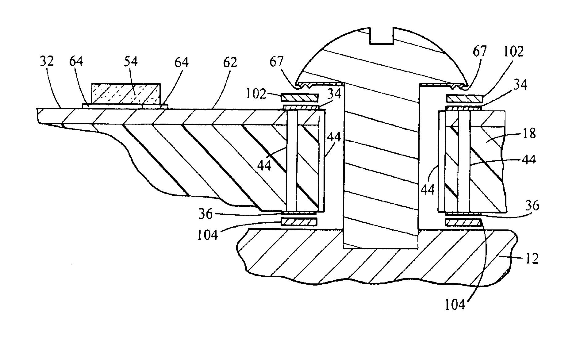
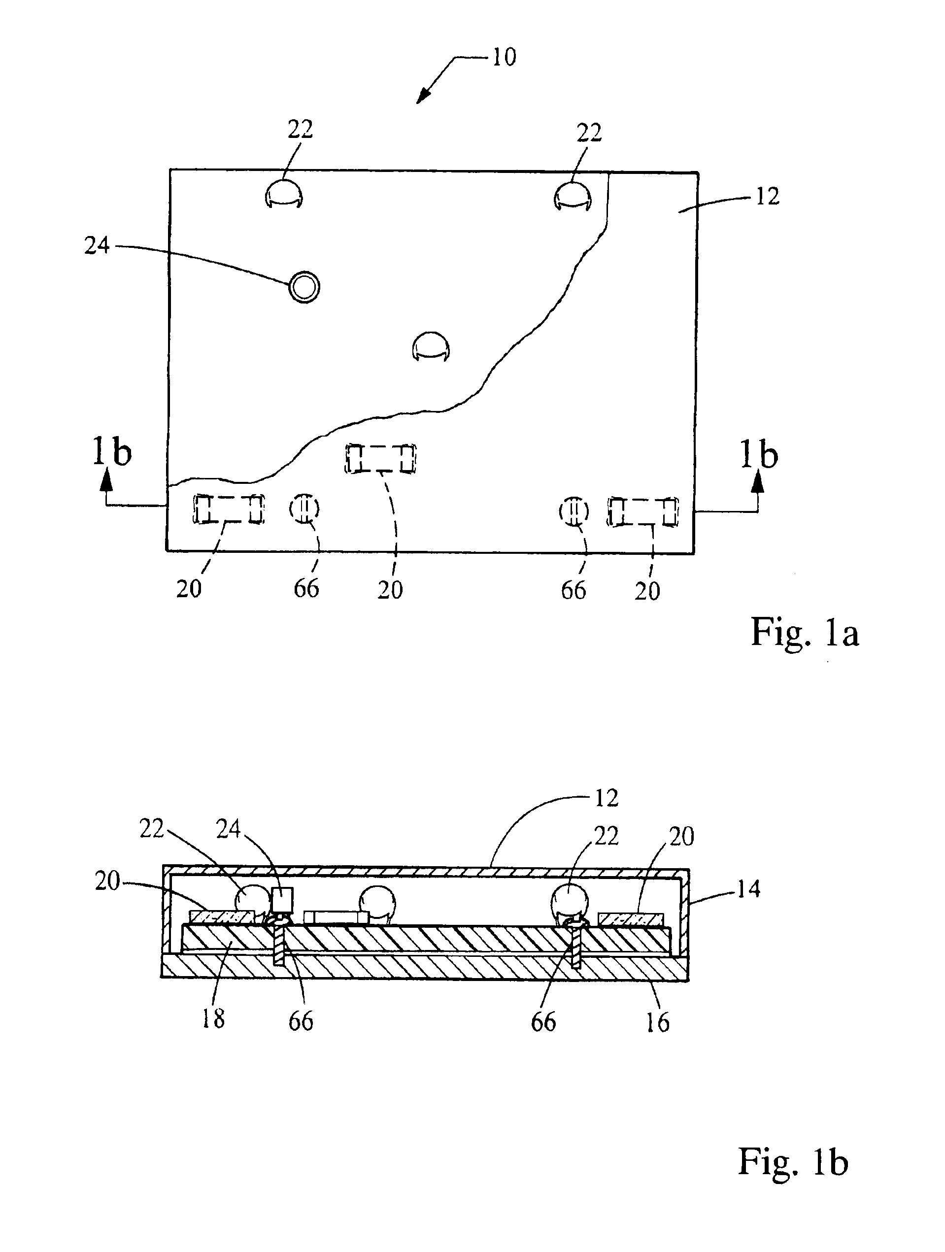
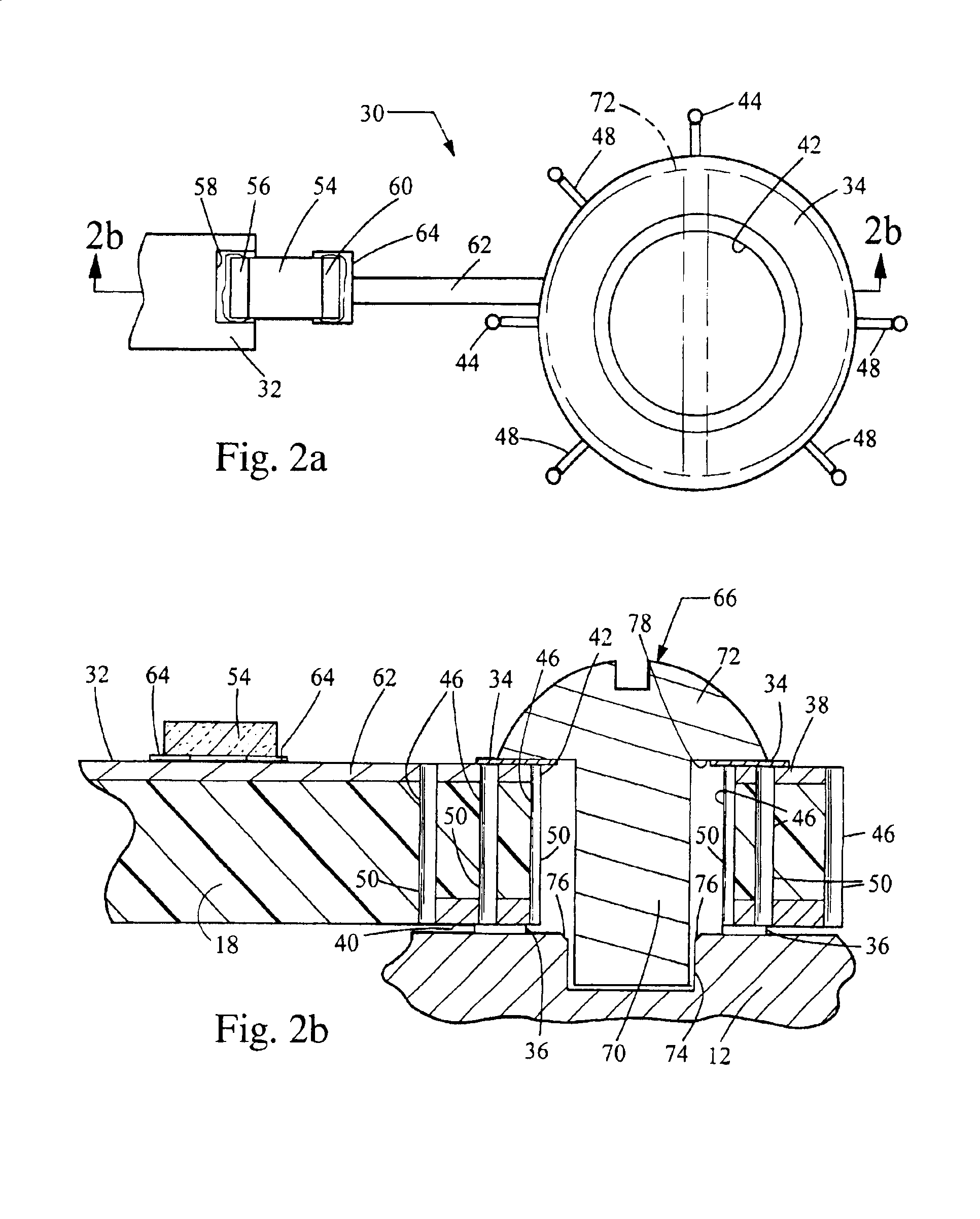
Referring now to FIGS. 1a and 1b, top and cross-sectional views of an electrical or electronic component 10, such as a powertrain control module (PCM) is illustrated, in accordance with the present invention. Electronic component or module 10 includes a housing 12 having a first cover portion 14 and a second cover portion 16. For example, first cover portion 14 may be a housing top cover and second cover portion 16 may be a housing bottom cover. Preferably, housing 12 is made of an electrically conductive material such as aluminum or the like. Further, module 10 includes an electronic circuit board 18, such as a printed circuit board (PCB). Generally, circuit board 18 is populated with electronic devices, such as resistors, capacitors, microcontrollers, inductors, etc. Circuit board 18 may be comprised of one layer or multiple layers.

Circuit board 18 is typically fastened to case 12 using a fastening means 19 such as a bolt or screw. For example, circuit board 18 may be fastened at ...


PUM


Abstract

An electronic module configured to suppress electromagnetic radiation is disclosed. The electronic module has a plurality of electronic components disposed therein. The module includes a module housing, a circuit board, and a plurality of capacitors. The module housing is made of an electrically conductive material. The circuit board has a ground plane and is fixed to the module housing. The plurality of capacitors are coupled at first end to the ground plane and at a second end to the housing. Further, the capacitors are connected electrically in parallel and are uniformly spaced within the electronic module.

Description

TECHNICAL FIELDThis invention relates generally to systems and methods for protecting electronic equipment from electromagnetic interference and to systems and methods for suppressing electromagnetic radiation.BACKGROUNDPowertrain Control Modules (PCMs), used in vehicles to control engines and power transmission systems, must not interfere with surrounding electronic components (radiated emissions) and must also be capable of operating normally when subjected to certain levels of electromagnetic radiation (radiated immunity).In some electronic control modules, a capacitor is placed in series between a copper ground plane of a printed circuit board (PCB) and a case ground, or metallic module housing. The metallic module housing is then mechanically and electrically joined to the vehicle's chassis via machine screws, brackets, or bolts, providing a substantially low impedance path for ground return currents to flow through. This design will provide some immunity to external electromag...

Claims


Application Information

Patent Timeline
IPC IPC(8): H05K9/00H05K1/02H05K1/11H05K3/32
CPCH05K1/0215H05K1/0231H05K1/116H05K9/0039H05K1/115H05K2201/10409H05K3/325H05K2201/0979H05K3/0061
Inventor TSANG, DAVID Y.JACOBS, GREGORY ALLENBELOKOUR, IGOR
Owner MICHIGAN MOTOR TECH LLC
Learn More