Multi-station HF FMCW radar frequency sharing with GPS time modulation multiplexing

a multi-station, time modulation multiplexing technology, applied in direction finders using radio waves, multi-channel direction-finding systems using radio waves, instruments, etc., can solve problems such as exacerbated problems, major disadvantages of sea echo mapping surface currents, and methods that are even more severe disadvantages than station sequencing

Inactive Publication Date: 2005-02-15
CODAR OCEAN SENSORS LTD
View PDF22 Cites 41 Cited by
  • Summary
  • Abstract
  • Description
  • Claims
  • Application Information

AI Technical Summary

Problems solved by technology

(ii) Only at these low frequencies can surface currents be extracted from the echo that is Bragg-scattered from the ocean waves; more prevalent microwave radars cannot measure surface currents, and alternative cost-effective measurement technologies do not exist.
The problem is exacerbated by the wide signal bandwidths needed for radar operation in contrast with radio communications.
This has a major disadvantage for mapping surface currents from sea echo.
This method has an even more severe disadvantage than station sequencing.
This is too costly a penalty to pay.
One unsatisfactory approach, used to address the above mentioned problem, is normal frequency multiplexing.
The problem with this method is that the spectral spacing between each frequency must be at least as great as the signal bandwidth.
Another principal obstacle with current technology is the inefficient use of spectral bandwidth resources by multiple radar transmitters and receivers, and inability to allow each radar to operate at maximal efficiency as though none of the other radars were present.
Heretofore, the requirements of an efficient use of radar resources, and the ability to operate multiple radars at a maximum efficiency referred to above have not been fully met.

Method used


Image

  • Multi-station HF FMCW radar frequency sharing with GPS time modulation multiplexing
  • Multi-station HF FMCW radar frequency sharing with GPS time modulation multiplexing
  • Multi-station HF FMCW radar frequency sharing with GPS time modulation multiplexing

Examples


Embodiment Construction

The invention and the various features and advantageous details thereof are explained more fully with reference to the nonlimiting embodiments that are illustrated in the accompanying drawings and detailed in the following description. Various substitutions, modifications, additions and / or rearrangements within the spirit and / or scope of the underlying inventive concept will become apparent to those skilled in the art from this disclosure.

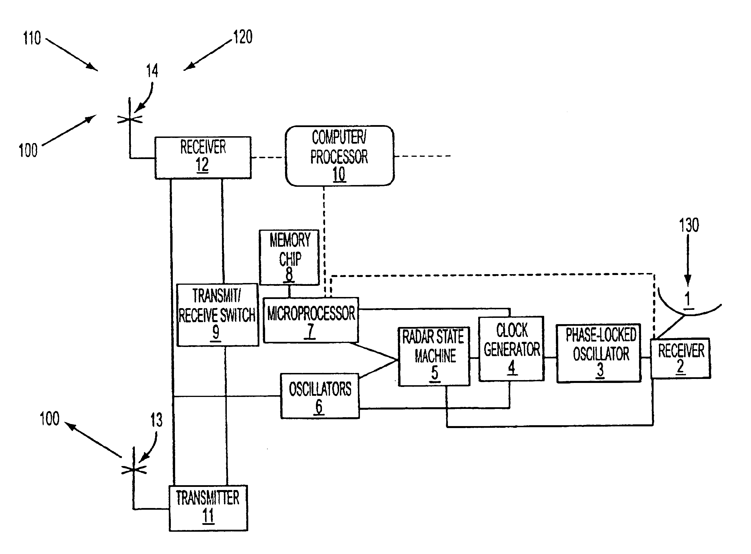
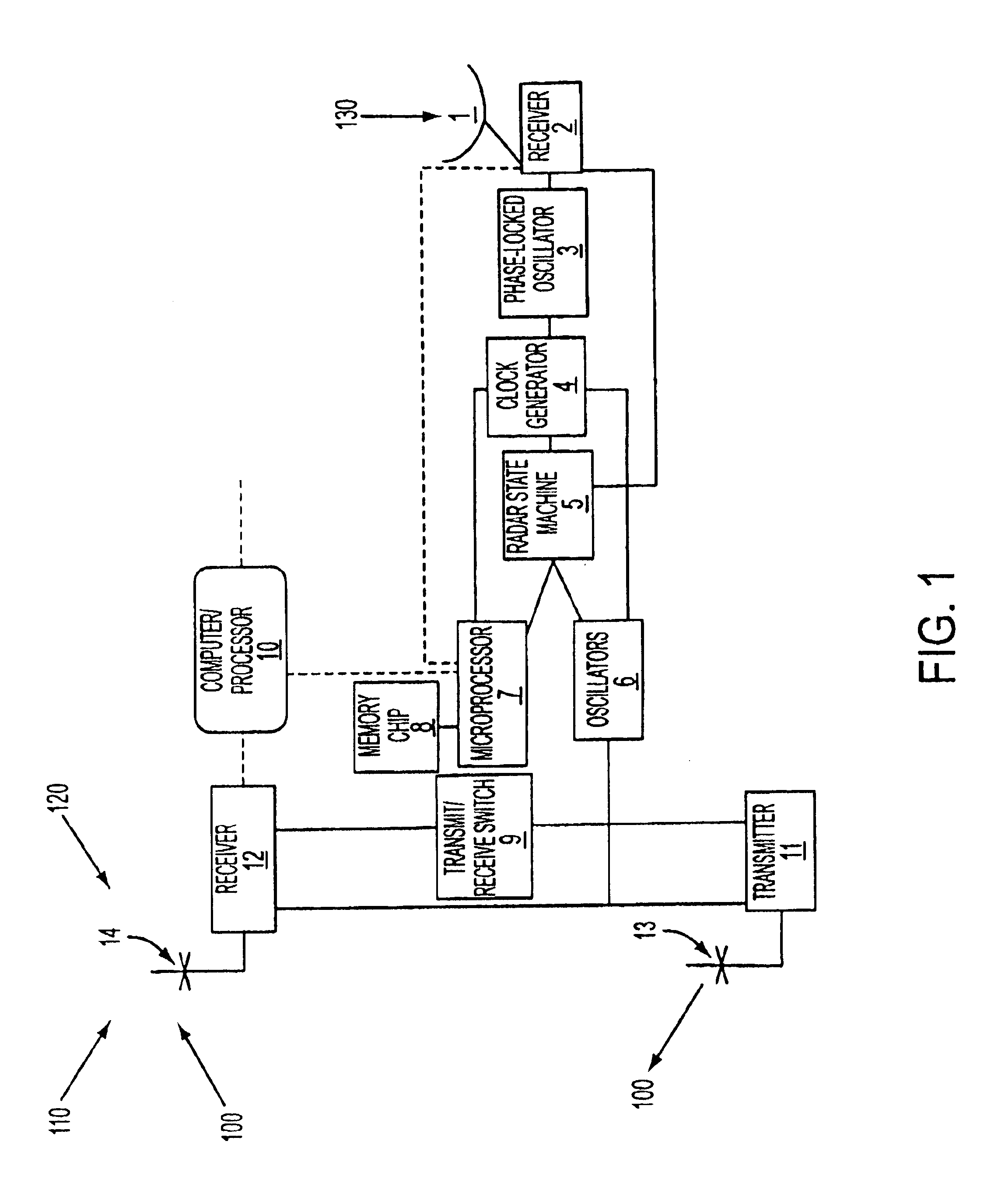
Techniques of the present disclosure can include providing a simple, inexpensive but precise, universally available timing base (GPS) that will allow synchronization of multiple backscatter radar users.

Techniques of the present disclosure can also include a mix of multiple backscatter and bistatic terminals, all operating simultaneously and sharing the same frequency but avoiding interference among each other.

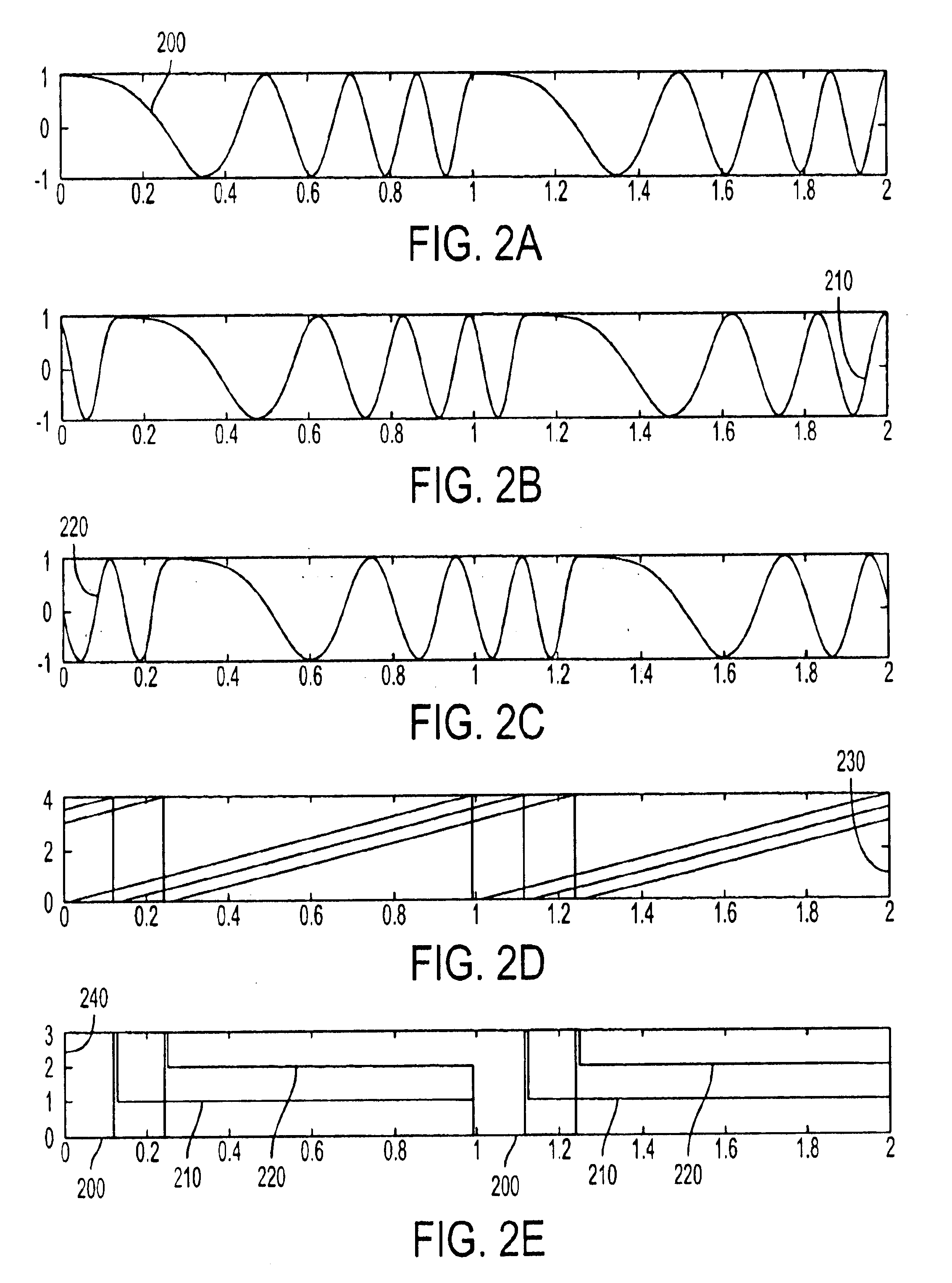
An unique opportunity is afforded by the waveform and signal processing employed by all of the coastal HF radars that follow the CODAR SeaSon...


PUM


Abstract

Systems and methods are described for HF radar frequency sharing with GPS time modulation multiplexing. A method is provided that includes generating clock signals from the time information contained in a GPS signal. Radio frequency signals are transmitted and received in a sequence whose start times are dictated by the clock signals. The clock signals also control the modulation of the radio frequency signals. The radio frequency signals are modulated by using a sweep modulation. An apparatus to implement the method includes a GPS receiver, a state machine, a clock generator, a microprocessor, a memory chip, a signal synthesizer, and a digital data output device. The GPS receiver extracts time information from GPS signals. The state machine controls radar functions versus time. The microprocessor performs modulation multiplexing on radar signals.

Description

BACKGROUND OF THE INVENTION1. Field of the InventionThe invention relates generally to the field of radars. More particularly, the invention relates to synchronization of multiple radars. Specifically, a preferred implementation of the invention relates to synchronization of multiple radars operating within the same frequency band.2. Discussion of the Related ArtLower-frequency radars, operating in the MF, HF, and VHF bands, have a number of uses. The primary application, however, has been the real-time mapping of ocean surface currents and local wave monitoring from coastal stations. For this purpose, these lower frequency radars offer many advantages. (i) With antennas sited at the coast, they have the ability to see beyond the horizon in the surface-wave propagation mode; lower frequencies achieve longer ranges. (ii) Only at these low frequencies can surface currents be extracted from the echo that is Bragg-scattered from the ocean waves; more prevalent microwave radars cannot me...

Claims


Application Information

Patent Timeline
Patent Type & Authority Patents(United States)
IPC IPC(8): G01S13/00G01S13/02G01S13/87G01S13/89G01S13/86G01S7/02G01S7/35G01S13/34G01S13/58G01S13/95G01S3/02G01S3/74G01S5/14G01S7/282G01S13/26G01S19/14G01S19/22G01S19/24
CPCG01S7/02G01S7/023G01S7/35G01S13/003G01S13/0218G01S13/86G01S13/87G01S13/89G01S3/74G01S19/14G01S13/589G01S13/951G01S13/343Y02A90/10G01S7/0235
Inventor BARRICK, DONALD E.LILLEBOE, PETER M.TEAGUE, CALVIN C.
Owner CODAR OCEAN SENSORS LTD
Why Eureka
Try Eureka