Methods and apparatus for attaching a heat sink to a circuit board component

a technology of circuit board components and heat sinks, which is applied in the direction of cooling/ventilation/heating modifications, semiconductor devices, semiconductor/solid-state device details, etc., can solve the problems of overheating and malfunction of the circuit board component, the adhesive properties of conventional thermally conductive adhesives degrade over time, and the gaps in conventional techniques for securing heat sinks to circuit boards. , to achieve the effect of minimizing the potential of the retainer, increasing the contact surface area

Inactive Publication Date: 2005-02-15
CISCO TECH INC
View PDF14 Cites 45 Cited by
  • Summary
  • Abstract
  • Description
  • Claims
  • Application Information

AI Technical Summary

Benefits of technology

In step 134, the assembler places a heat sink 38 in thermal communication with the circuit board component 40. In one arrangement, the assembler places a thermal interface material (e.g., thermally conductive putty such as Fuji-Poly) between the circuit board component 40 and the heat sink 38. The thermal interface material minimizes the presence of gaps between the heat sink 38 and circuit board component 40, thereby increasing the contacting surface areas between the heat sink 38 and the ci...

Problems solved by technology

Conventional techniques for securing a heat sink to a circuit board component suffer from a variety of deficiencies.
However, the adhesive properties of conventional thermally conductive adhesives degrade over time.
Over time, therefore, the heat sink can disassociate from the circuit board component and lead to overheating and malfunction of the circuit board component.
Furthermore, certain circuit board components have a relatively large power requirement and utilize relatively large heat sinks to dissipate the heat generated by such circuit board components during operation.
As the thermally conductive a...

Method used


Image

  • Methods and apparatus for attaching a heat sink to a circuit board component
  • Methods and apparatus for attaching a heat sink to a circuit board component
  • Methods and apparatus for attaching a heat sink to a circuit board component

Examples


Embodiment Construction

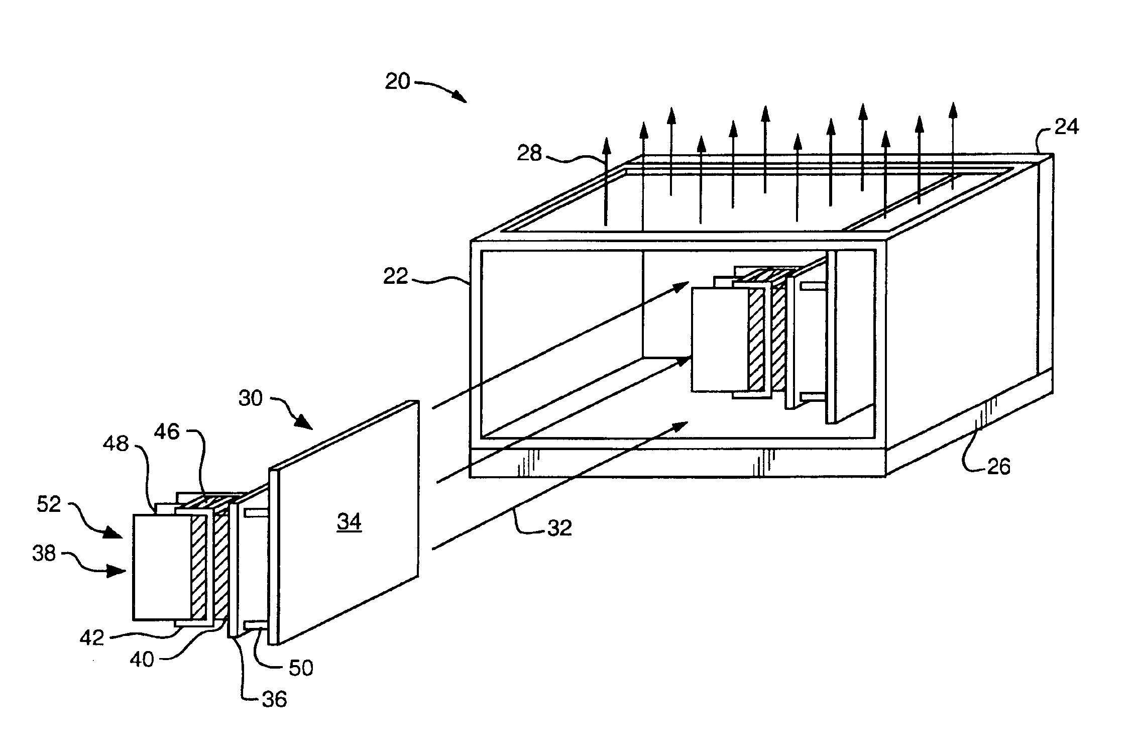
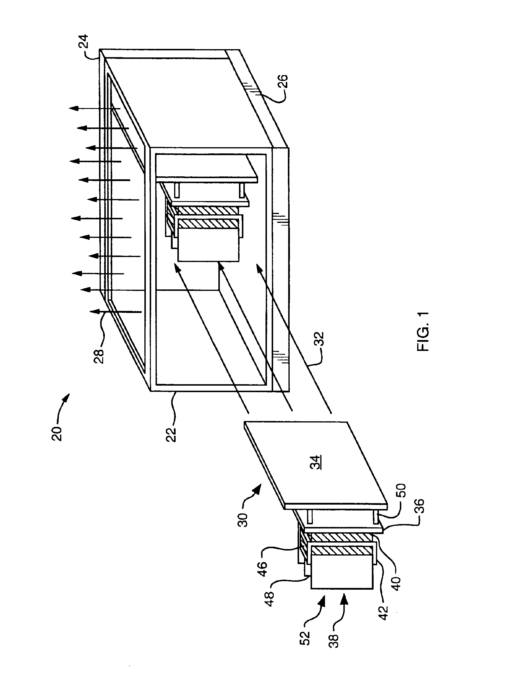
Embodiments of the present invention provide mechanisms for securing a heat sink to a circuit board component. A retainer directly attaches to the circuit board component and to the heat sink and secures the circuit board component to the heat sink. The retainer provides a mechanical attachment between the heat sink and the circuit board component. Such mechanical attachment maintains thermal communication between the heat sink and the circuit board component in the absence of a thermally conductive adhesive between the heat sink and the circuit board component for the operational life of the circuit board component. Furthermore, because the retainer attaches directly to the circuit board component and to the heat sink, the retainer minimizes the necessity for use of mounting holes in the circuit board associated with the circuit board component to secure the heat sink to the circuit board component.

FIG. 1 shows a computer system 20, suitable for use of the invention. The computer s...


PUM


Abstract

A retainer directly attaches to a circuit board component and to a heat sink and secures the circuit board component to the heat sink. The retainer provides a mechanical attachment between the heat sink and the circuit board component. Such mechanical attachment maintains thermal communication between the heat sink and the circuit board component in the absence of a thermally conductive adhesive between the heat sink and the circuit board component for the operational life of the circuit board component. Furthermore, because the retainer attaches directly to the circuit board component and to the heat sink, the retainer minimizes the necessity for use of mounting holes in the circuit board associated with the circuit board component to secure the heat sink to the circuit board component.

Description

BACKGROUNDA typical circuit board assembly includes a circuit board formed of circuit board materials (e.g., fiberglass, copper, etc.) and circuit board components mounted to the circuit board. Examples of circuit board components include integrated circuits (ICs), resistors, and inductors. Certain conventional ICs, such as ball grid array (BGA) devices, have an array of solder balls that attach to contact pads, for example, located on the circuit board. The array of solder balls provides mechanical attachment of the BGA device to the circuit board (e.g., attachment to the contact pads of the circuit board) and provides electrical contact between the BGA device and the circuit board.Conventionally, circuit board components generate heat during operation. A fan assembly typically generates an air stream that passes over, and carries the heat away from, the circuit board components. The air stream removes the heat so that the components do not operate in an unsafe temperature range, i...

Claims


Application Information

Patent Timeline
IPC IPC(8): H01L23/40H01L23/34
CPCH01L23/4093H01L2224/16
Inventor VIERNES, RAINIERCHERN, MICHAEL
Owner CISCO TECH INC
Why Eureka
Try Eureka