Wavelength monitor utilizing a tunable bragg grating and blazed grating

a technology of blazed grating and tunable bragg grating, which is applied in the direction of optical resonator shape and construction, instruments, optical elements, etc., can solve the problems of limiting the ultimate performance of the device, increasing the number of inoperable pixels, and limiting the device's price, so as to achieve a higher resolution wavelength discriminator and less costly components

Inactive Publication Date: 2005-02-15
II VI DELAWARE INC
View PDF1 Cites 2 Cited by
  • Summary
  • Abstract
  • Description
  • Claims
  • Application Information

AI Technical Summary

Benefits of technology

One advantage of the present invention is that it enables the use of less costly components and produce a higher resolution wavelength discriminator. For example, a much less expensive detector may be used to ...

Problems solved by technology

However, this technique has several drawbacks which limit its ultimate performance.
If more resolution is desired, then an array with additional detectors (such ...

Method used


Image

  • Wavelength monitor utilizing a tunable bragg grating and blazed grating
  • Wavelength monitor utilizing a tunable bragg grating and blazed grating
  • Wavelength monitor utilizing a tunable bragg grating and blazed grating

Examples


Embodiment Construction

FIG. 2: The Basic Invention

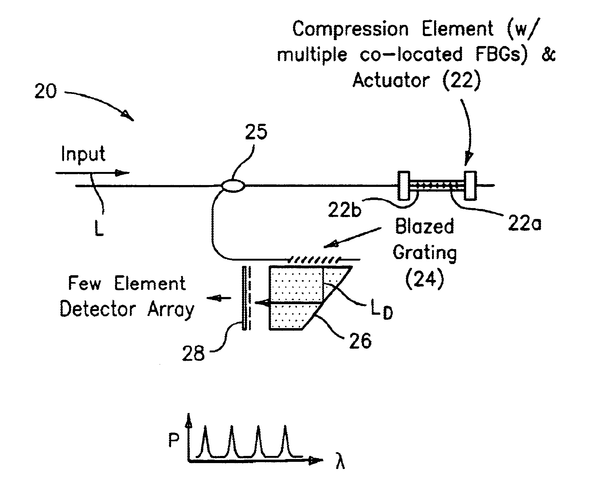
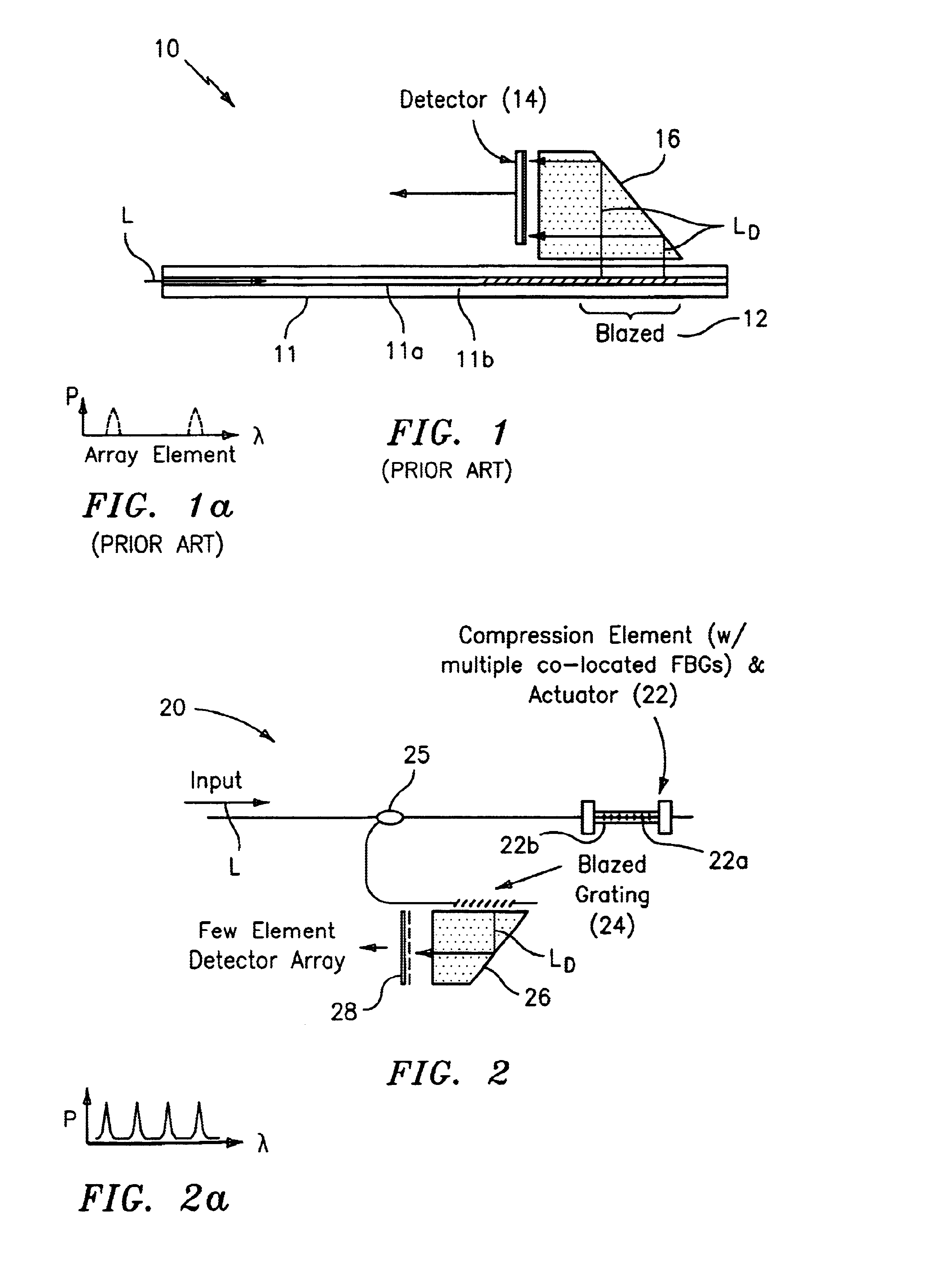
FIG. 2 shows, by way of example, a wavelength monitoring device or system generally indicated as 20 in accordance with the present invention. The wavelength monitoring device 20 has a compression element and actuator generally indicated as 22 with a Bragg grating 22a and has a blazed grating 24. In operation, the incoming light L is directed from a coupler 25 onto one or more Bragg gratings 22a located in a glass element 22b which serve to spectrally process the incoming optical signal L. The reflected components of the light L are then directed via the coupler 25 onto the blazed grating 24 which reflects the light out of the fiber core onto a detector array 28. The decoupled light LD is reflected through a member 26. In this configuration, the resolution of the wavelength monitoring device 20 is determined primarily by the one or more Bragg gratings 22a, which reflect only a narrowband portion of the incoming light determined by a bandwidth and shape of a...


PUM


Abstract

A wavelength monitoring device is provided having an optical reflecting element for reflecting an incoming optical signal to a detector, wherein the device features a narrowband optical reflecting element for reflecting only a narrowband portion of the incoming optical signal to the optical reflecting element. The narrowband optical reflecting element has a reflection function having a bandwidth and shape that determines the narrowband portion of the incoming optical signal. The narrowband optical reflecting element may be a Bragg grating for spectrally processing the incoming optical signal, while the optical reflecting element may be a blazed Bragg grating for reflecting the spectrally processing incoming optical signal to the detector. The detector determines an amount of optical power reflected by the Bragg grating and discriminates between reflections of individual gratings, and is a spatial filter for providing a direct correlation between individual detector elements and a specific wavelength range. The narrowband optical reflecting element includes a glass element having a Bragg grating arranged therein. The glass element may be either an optical fiber having a diameter of about 125 microns, or a large diameter waveguide having a diameter of at least about 0.3 millimeters.

Description

BACKGROUND OF THE INVENTION1. Technical FieldThe present invention generally relates to an optical system; and more particularly to an system for monitoring the wavelength or some other optical parameter of an optical signal.2. Description of Related ArtFIG. 1 shows a wavelength monitoring device 10 that is known in the art, constructed using an optical fiber 11 having a fiber core 11a, a cladding 11b surrounding the fiber core 11a and a blazed fiber Bragg grating 12 written in the fiber core 11a, and used in conjunction with a detector array 14, as shown and described in U.S. Pat. No. 6,002,822, issued to Lucent Technologies, Inc., which is hereby incorporated by reference in its entirety. (See also U.S. Pat. No. 5,337,382 which discloses a 125 micron optical fiber having Bragg gratings written therein at an oblique angle, which are known in the art as blazed gratings, which is also incorporated by reference herein.)In FIG. 1, the blazed fiber grating 12 is used to decouple light g...

Claims


Application Information

Patent Timeline
IPC IPC(8): G02B6/34
CPCG02B6/022G02B6/2932G02B6/29322G02B6/4215G02B6/2938G02B6/29385G02B6/29398G02B6/29323G02B6/02176
Inventor DAVIS, MICHAEL A.KERSEY, ALAN D.
Owner II VI DELAWARE INC
Why Eureka
Try Eureka