Intelligent network topology and configuration verification using a method of loop detection

a topology verification and intelligent network technology, applied in the field of communications network topology configuration verification using a loop detection method, can solve the problems of prohibitively expensive implementation of spanning tree algorithm on relatively low cost bridging devices, inability to achieve the spanning tree algorithm in time, so as to reduce the likelihood and reduce the cost. the effect of cost and low cos

Inactive Publication Date: 2005-02-15
HEWLETT-PACKARD ENTERPRISE DEV LP +1
View PDF9 Cites 69 Cited by
  • Summary
  • Abstract
  • Description
  • Claims
  • Application Information

AI Technical Summary

Benefits of technology

In one example of how the disclosed system can be extended, the bridge type input/output device further operates to prevent relatively complex network topologies from being connected to one or more of its external communications ports by monitoring those external communications ports for routing protocol messages. In such an extended system, in the event that a routing protocol message is detected on one of those external communications ports, the bridge type input/output module disables the port. By disabling a port which receives a routing protocol message, this example of an extension to the disclosed system prevents network topologies which include routers, and which therefore are likely to be relatively large and contain many nodes, from being connected to its external ports.
In this way there is provided a system and method for detecting and eliminating bridge loops which are appropriate for use

Problems solved by technology

As it is generally known, in a local area network (LAN) using a protocol such as Ethernet or Token Ring, devices referred to as “nodes” compete for the ability to use a shared communications path to exchange messages referred to as “data units” or “frames.” However, if too many nodes consistently attempt to transmit simultaneously, the overall performance of the network may potentially be affected, even to the point of bringing communications over the network to a near halt.
A known problem relating to the use of bridge technology is the need to avoid what are referred to as “broadcast storms.” Broadcast storms may occur when bridges are connected in a physical loop, which results in a logical loop sometimes referred

Method used


Image

  • Intelligent network topology and configuration verification using a method of loop detection
  • Intelligent network topology and configuration verification using a method of loop detection
  • Intelligent network topology and configuration verification using a method of loop detection

Examples


Embodiment Construction

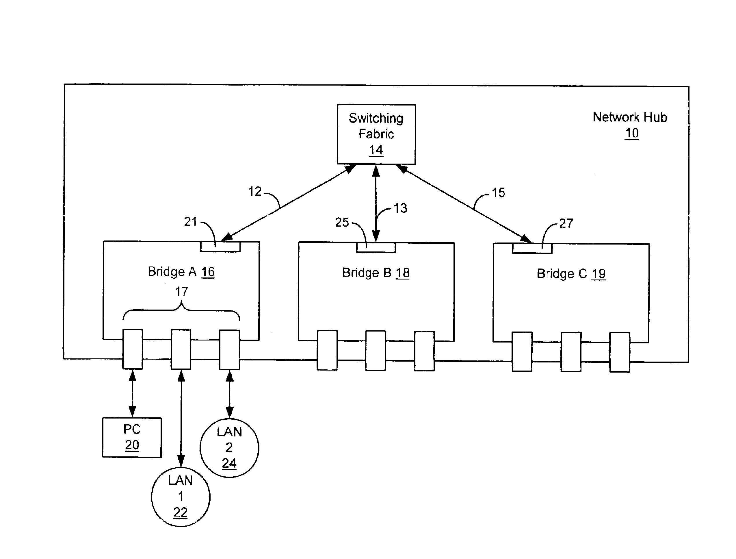
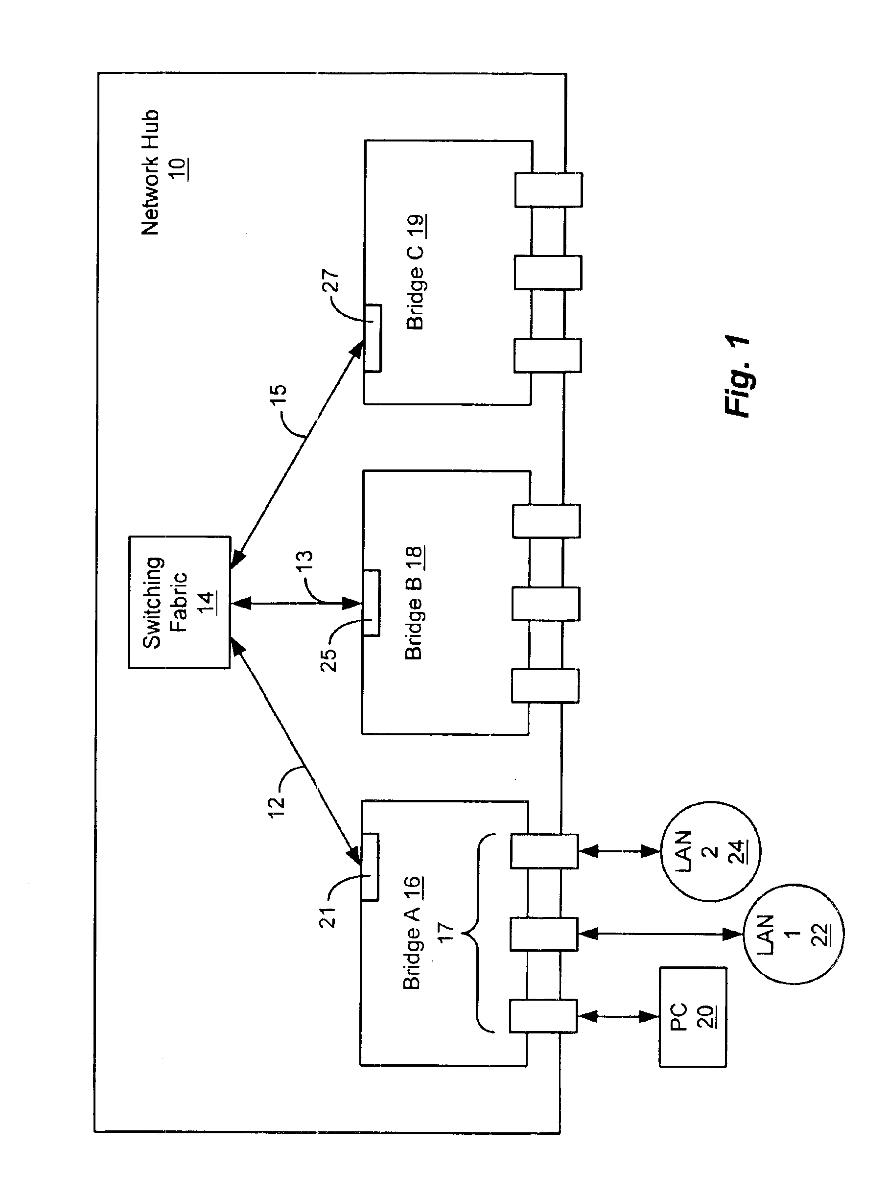
As depicted in FIG. 1, in an illustrative embodiment of the disclosed system, a network hub 10 includes a switching fabric 14, a number of bridge type I / O modules, shown as bridge A 16, bridge B 18 and bridge C 19, and point to point connections 12, 13 and 15 interconnecting the bridge type I / O modules to the switching fabric 14. The point to point connections 12, 13 and 15 each terminate at one of backplane ports 21, 25 and 27 within a respective one of the bridge type I / O modules 16, 18 and 19. In this way, the point to point connections 12, 13 and 15 form a star wired backplane. The star wired backplane illustrated by point to point connections 12, 13 and 15 in FIG. 1 is referred to herein as the “backplane”.

Each of the bridge type I / O modules in the network hub 10 of FIG. 1 includes a number of external communication ports, shown as external communication ports 17 in bridge A 16. Each of the external communication ports of the bridges shown in FIG. 1 may be coupled to an end sta...


PUM


Abstract

A system and method are disclosed for detecting and preventing bridge loops in a relatively low cost bridge module designed for installation in a network hub. The bridge operates to monitor an intra-hub communication path of the network hub to detect bridge protocol data units transmitted by a switching fabric within the network hub. The bridge module stores a MAC source address of a bridge protocol data unit detected on the intra-hub communications path, and forwards the bridge protocol data unit through its external communication ports to respective network segments. The bridge module monitors its external communication ports for any data unit having a destination address matching a bridge multicast address. When a data unit having a destination address matching the bridge multicast address is detected, the bridge module compares the MAC source address of that data unit to the previously stored MAC source address from the bridge protocol data unit detected on the intra-hub communication path. In the event that the MAC source address of the data unit detected on the external communication port matches the previously stored MAC source address, the bridge module disables operation of the respective one of its external communication ports at which the data unit was received. In one embodiment of the disclosed system, the bridge module further monitors its external communications ports for routing protocol messages. In the event that a routing protocol message is detected on one of those external communications ports, the bridge module disables that port.

Description

CROSS REFERENCE TO RELATED APPLICATIONSN / ASTATEMENT REGARDING FEDERALLY SPONSORED RESEARCH OR DEVELOPMENTN / ABACKGROUND OF THE INVENTIONThe present invention relates generally to configuring the topology of a communications network, and more specifically to a system and method for detecting and eliminating network loops connected to a bridge device installed in a networking hub.As it is generally known, in a local area network (LAN) using a protocol such as Ethernet or Token Ring, devices referred to as “nodes” compete for the ability to use a shared communications path to exchange messages referred to as “data units” or “frames.” However, if too many nodes consistently attempt to transmit simultaneously, the overall performance of the network may potentially be affected, even to the point of bringing communications over the network to a near halt. To make this possibility less likely, large LANs are often divided into two or more LAN segments connected by one or more networking devi...

Claims


Application Information

Patent Timeline
IPC IPC(8): G06F15/16G06F15/173H04L12/46
CPCH04L12/46
Inventor LINDEBORG, CARL JOHNMOREAU, MARK DAVIDPETRY, KEITH LOUISZIEGLER, JOHN ERNEST
Owner HEWLETT-PACKARD ENTERPRISE DEV LP
Why Eureka
Try Eureka