Supercharge Your Innovation With Domain-Expert AI Agents!

Extension for the advanced microcontroller bus architecture (AMBA)

a technology of advanced microcontrollers and bus architectures, applied in the direction of instruments, liquid/fluent solid measurement, generating/distributing signals, etc., can solve the problems of inability to interchange peripherals, congestion is likely to occur, and there is no standardised solution to this problem, so as to improve amba, reduce power consumption of apb functional blocks, and improve the effect of amba

Inactive Publication Date: 2005-02-15
FUTURE LINK SYST
View PDF5 Cites 19 Cited by
  • Summary
  • Abstract
  • Description
  • Claims
  • Application Information

AI Technical Summary

Benefits of technology

It is an object of the present invention to provide a scheme for enhancing AMBA by adding a reusable design methodology for reducing the power consumption of APB functional blocks.
It is an object of the present invention to provide a system and method that can be driven at a lower clock speed and that leads to a reduced power consumption.
It is an advantage of the present scheme that functional blocks in an APB domain can be run at a lower clock speed than the AHB- or ASB domain's clock speed, and that the power consumption is reduced.
It is an advantage of the present invention that peripheral subsystems can be easily combined with an embedded ARM core. Custom ASICs can be realised more easily.

Problems solved by technology

There is no standardised solution to this problem.
Since there is no standardised solution, the peripherals are not interchangeable.
A problem occurs if a functional block within the high clock frequency domain (i.e., within the AHB- or ASB-domain) transfers data to a functional block in the low clock frequency domain (e.g., within the APB domain).
Since the functional block in the low clock frequency domain is not able to cope with the amount of data transmitted by the functional block in the high clock frequency domain, a congestion is likely to occur.

Method used


Image

  • Extension for the advanced microcontroller bus architecture (AMBA)
  • Extension for the advanced microcontroller bus architecture (AMBA)
  • Extension for the advanced microcontroller bus architecture (AMBA)

Examples


first embodiment

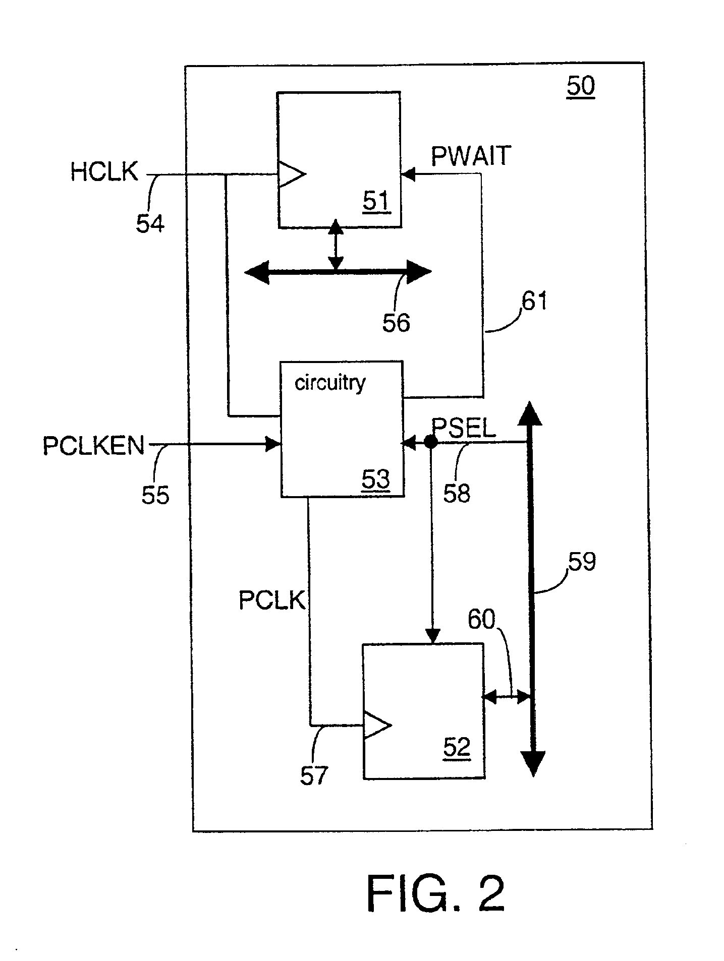
A first embodiment is described in connection with FIG. 2. A SoC 50 is illustrated in this Figure. It comprises a high-speed functional block 51 and a system bus 56 (high-speed bus). The high-speed functional block 51 receives a high-speed clock (HCLK) via a high-speed clock line 54.

In addition to the system bus 56, the system 50 also comprises a peripheral bus 59 (low-speed bus). In the present embodiment, a low-speed functional block 52 is connected to the bus 59, as indicated by the arrow 60. The functional block 52 can send information (e.g., data) to the peripheral bus 59 and it can receive information from the peripheral bus 59. According to the present invention, a circuitry 53 is provided. This circuitry 53 and the functional block 52 receive a select signal (PSEL) via the peripheral bus 59 and select line 58. This select signal (PSEL) is issued by a central address decoder (not shown in FIG. 2), for example. In the present example, the PSEL is assumed to be issued in order ...


PUM


Abstract

System (50), e.g. a System on a chip (SoC), comprising a system bus (56), a high-speed functional block (51) operably linked to the system bus (56), and a high-speed clock line (54) for applying a high-speed clock to the high-speed functional block (51). The system (50) further comprises a peripheral bus (59), a low-speed functional block (52) operably linked to this peripheral bus (59), a circuitry (53) for generating a wait signal (PWAIT), a low-speed clock line (57) for applying a low-speed clock (PCLK) to the low-speed functional block (52), a select line (58) for feeding a select signal (PSEL) from the peripheral bus (59) to the low-speed functional block (52), an enable line (55) for applying a clock enable signal (PCLKEN) to the circuitry (53), and a wait line (61) for feeding the wait signal (PWAIT) to the high-speed functional block (51). The circuitry (53) generates the wait signal (PWAIT) from the select line signal (PSEL) and the clock enable signal (PCLKEN).

Description

FIELD OF THE INVENTIONThe present invention concerns generally the interconnection and management of functional blocks of an Advanced Peripheral Bus (APB) with functional blocks in the domain of the Advanced High-performance system Bus (AHB) or the Advanced System Bus (ASB). In particular, the present invention concerns an extension of the AMBA-APB architecture that allows APB-peripherals to be connected to the functional blocks within the AHB or ASB domain.BACKGROUND OF THE INVENTIONAs the demand for more powerful and flexible computing devices increases, more and more Systems-on-Chip (SoC) are being developed. Many SoCs comprise Application Specific Integrated Circuits (ASICs) that are offered by several companies.The Advanced RISC Machines (ARM) microprocessor is very popular for SoC solutions. Today it is fair to say that the ARM Embedded Technology is universally recognised as an industry standard for ASIC design for portable applications. Creating and applying powerful, portab...

Claims


Application Information

Patent Timeline
IPC IPC(8): G06F13/00G06F1/08G06F13/40G06F13/42G06F1/06G06F1/04
CPCG06F13/4054Y02B60/1235Y02B60/1228Y02D10/00G06F2213/0038
Inventor MESSMER, ADRIANKOCH, STEFAN
Owner FUTURE LINK SYST
Features
  • R&D
  • Intellectual Property
  • Life Sciences
  • Materials
  • Tech Scout
  • Unparalleled Data Quality
  • Higher Quality Content
  • 60% Fewer Hallucinations
Learn More