
Sample probe for aerosol sampling apparatus

a sampling apparatus and probe technology, applied in the field of sampling devices, can solve the problems of insufficient inability to conveniently fit inside the wall cavity of the sampling cassette, and inability to manufacture, etc., and achieve the effect of sufficient diameter of the probe, reduced manufacturing costs, and reduced cross contamination between samples

Inactive Publication Date: 2005-02-22
SPURGEON JOE C
View PDF5 Cites 14 Cited by
  • Summary
  • Abstract
  • Description
  • Claims
  • Application Information

AI Technical Summary

Benefits of technology

Briefly, and in general terms, the present invention addresses the aforementioned disadvantages by providing an improved sample probe adapted to be inserted into a wall cavity for sampling aerosols. The probe is sufficiently inexpensive to manufacture that it can be replaced between samples so as to be essentially disposable. The difficulties of cleaning, and cross contamination between samples is therefore eliminated. Moreover, the improved wall probe is not prone to crimping, blockage, and the diameter of the probe is sufficiently large so as to eliminate the need for a protective cap and metal rod.
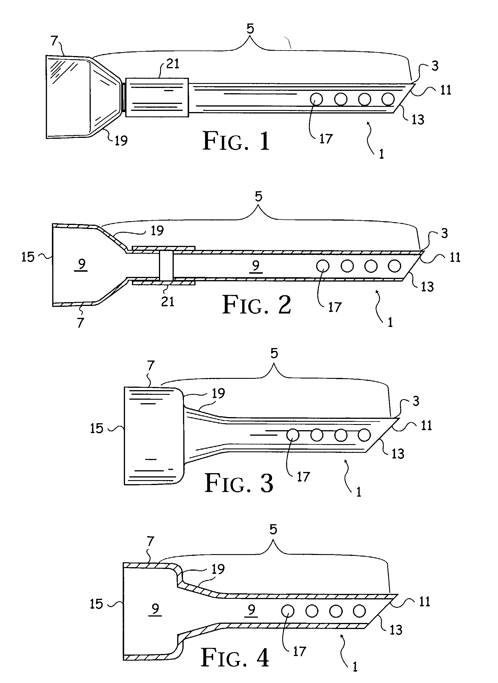
To this end, the wall sampling probe includes a hollow tubular body having a distal open inlet, an intermediate portion, a proximal open outlet and a central passageway extending the length of the tubular body. Of importance, the distal open inlet of the aerosol sampling apparatus is beveled to form a sharp point. The beveled sharp point construction is provided to reduce the propensity of the distal end to become clogged due to the distal end engaging an obstruction, such as the rear portion of the wall. In particular, when positioned against an obstruction, the sharp point of the beveled distal opening engages the obstruction, allowing the withdrawal of air and particulates to tangentially enter the beveled opening.
It is therefore an object of the present invention to provide for a wall sampling probe which is inexpensive to manufacture, and thus disposable between air sampling procedures. Therefore, the probe eliminates the possibility of cross contamination from previously collected samples, and the elimination of the need to clean the wall probe between samples.
It is still an additional object of the present invention to provide a wall probe which includes a central passageway which is sufficiently large that clogging by dust and debris is not a practical concern and the need for a protective cap and disgorging metal rod is eliminated.

Problems solved by technology

Unfortunately, none of the above described air collection devices, also referred to as sampling cassettes, are suitable for aerosol sampling within a wall cavity.
In particular, such cassettes are too large to conveniently fit inside a wall cavity.
Unfortunately, the WallChek® device is extremely expensive, costing several hundred dollars.
Because of this high cost, the WallChek® assembly is typically reused, with subsequent samples requiring the use of the same hood and flexible tube assembly.
This prior art construction is thus susceptible to contamination from prior sampling.
Unfortunately, this is an often difficult task to perform, particularly when sampling is conducted in the field where cleaning facilities are not available.
An additional disadvantage of the WallChek® system is that the internal diameter of the flexible tube is relatively small causing the tube to be easily clogged by dust and debris generated when the hole is formed in a wall by punching or drilling through drywall or plaster.
Though a protective cap is provided when inserting the tube into the wall, the process for removing the cap with a metal rod is cumbersome and time consuming.
Still an additional disadvantage with the prior art wall cavity sample probe is that it uses a thin flexible plastic tube which has only a single opening at the tip of the tube.
The opening of the tube is prone to becoming blocked if positioned against a solid object within the wall cavity, such as the wall structure at the rear of the wall cavity.
Moreover, if the tube encounters an object within the wall cavity during insertion, the tube is prone to bending sharply, causing crimping of the tube and a reduction in the amount of airflow into the sampling cassette which can effect the integrity of the sample.

Method used


Image

  • Sample probe for aerosol sampling apparatus
  • Sample probe for aerosol sampling apparatus
  • Sample probe for aerosol sampling apparatus

Examples


Embodiment Construction

While the present invention is susceptible of embodiment in various forms, as shown in the drawings, hereinafter will be described the presently preferred embodiments of the invention, with the understanding that the present disclosure is to be considered as an exemplification of the invention, and it is not intended that the invention be limited to the specific embodiments illustrated.

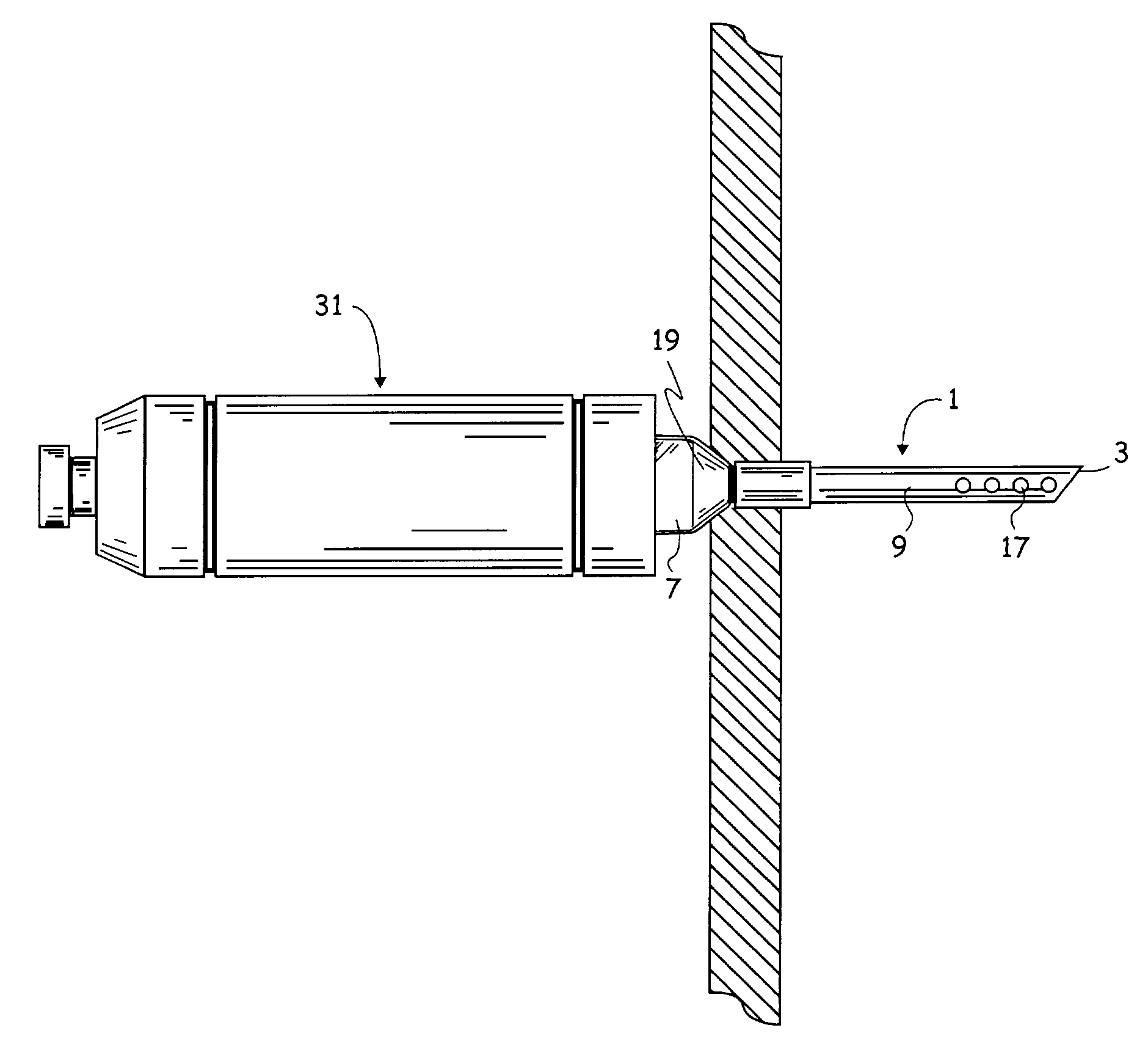
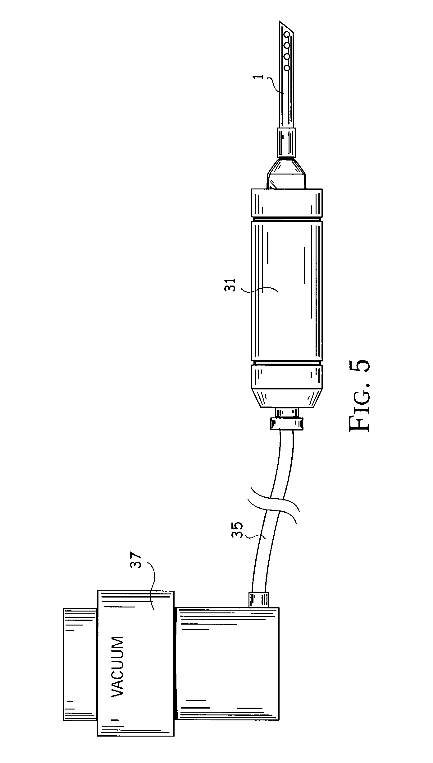
With reference to the figures, and particularly FIGS. 1-4, the sample probe 1 of the present invention includes a distal end 3, an intermediate portion 5, and a proximal end 7. The sample probe 1 is substantially tubular, and thus hollow, forming a central passageway 9 which extends the entire length of the sample probe.

The distal end 3 of the probe includes an open inlet 13 which is beveled forming a sharp point 11. The angle of the bevel may vary greatly as determined by those skilled in the art, depending on various factors such as the material and thickness of the wall, the material being penet...


PUM


Abstract

A sample probe is provided for sampling aerosols within a wall cavity. The sample probe includes a hollow tubular body having a distal end, an intermediate portion, a proximal end and a central passageway. The distal end includes a sharp beveled point provided to inhibit the blockage of a distal open inlet if the distal end is positioned against an object. The probe further includes one or more holes projecting through the probe's tubular body, preferably positioned substantially adjacent to the probe's distal end. The probe further includes a radially projecting region adapted for sealing a hole or opening formed to obtain access to a wall cavity. Moreover, the probe includes a proximal open outlet adapted to connect to the inlet of an aerosol sampling cassette.

Description

BACKGROUND OF THE INVENTION The present invention relates to sampling devices for capturing airborne or liquid-suspended particles. More specifically, the present invention relates to an apparatus for collecting aerosols from wall cavities. As used herein, reference to wall cavities is intended to be given the broadest interpretation including cavities within wall structures, ceiling structures, and the like. There are numerous prior art filter sampling devices available today. A typical filtration cassette has an inlet and outlet for directing the flow of an initial sample medium, either liquid or gas. Using a vacuum source, gas and / or liquid molecules, as well as particles, are made to pass through the filter medium. The filter medium selectively retains particles based on the particle's size. An additional conventional air sampling device is commercially available under the trade name, Air-O-Cell®. This air sampler includes a two part cassette having a narrowing inlet and an outl...

Claims


Application Information

Patent Timeline
IPC IPC(8): G01N1/22
CPCG01N1/2202G01N1/2226G01N2001/2285
Inventor SPURGEON, JOE C.
Owner SPURGEON JOE C
Learn More