Control system for internal combustion engine

a control system and internal combustion engine technology, applied in the direction of electric control, engine starters, braking systems, etc., can solve the problems of adversely affecting the drivability or exhaust emissions, airflow to be sucked, and not detected by the airflow meter, so as to reduce the amount of airflow flowing, suppress the dispersions in the starting condition and the emissions, and reduce the residual pressure

Inactive Publication Date: 2005-02-22
DENSO CORP +1
View PDF3 Cites 26 Cited by
  • Summary
  • Abstract
  • Description
  • Claims
  • Application Information

AI Technical Summary

Benefits of technology

Alternatively, the brake booster residual pressure adjusting means may include a bypass passage for bypassing a check valve disposed in the vacuum introducing passage which communicates the intake pipe with the brake booster and an orifice for reducing the amount of airflow flowing through the bypass passage. With this construction, the air in the intake pipe can be gradually fed during the stop of the internal combustion engine through the orifice of the bypass passage into the brake booster thereby to lower the residual pressure gradually, so that the residual pressure of the brake booster can be set substantially to the atmospheric pressure (i.e., the pressure equal to the intake pipe) during the stop of the internal combustion engine. As a result, the residual pressure of the brake booster at the beginning of the start can be made substantially atmospheric every times so that the airflow to be sucked from the brake booster into the intake pipe at the starting time can be made substantially constant every times.
On the other hand, the control system may further comprise suction airflow information detecting means for detecting the information (as will be called the “suction air

Problems solved by technology

However, the vacuum introducing passage of the brake booster is connected to the intake pipe downstream of the airflow meter (i.e., downstream of the throttle valve), so that the airflow to be sucked from the brake booster via the vacuum introducing passage into the intake pipe is not detected by the airflow meter.
Therefore, the air/fuel ratio may be changed into the lean direction to lower the torque or increase the NOx emissions thereby to adversely affect the drivability or the exhaust emissions.
If, however, the driver depresses the brake pedal while the internal combustion engine is stopped (or before the engine start), the residual pressure of the brake booster drops.
With the engine at starting, the air/fuel ratio may be changed into the lean direction by the influences of the air sucked from the brake booster into the intake pipe, to lower the torque

Method used


Image

  • Control system for internal combustion engine
  • Control system for internal combustion engine
  • Control system for internal combustion engine

Examples


first embodiment

(First Embodiment)

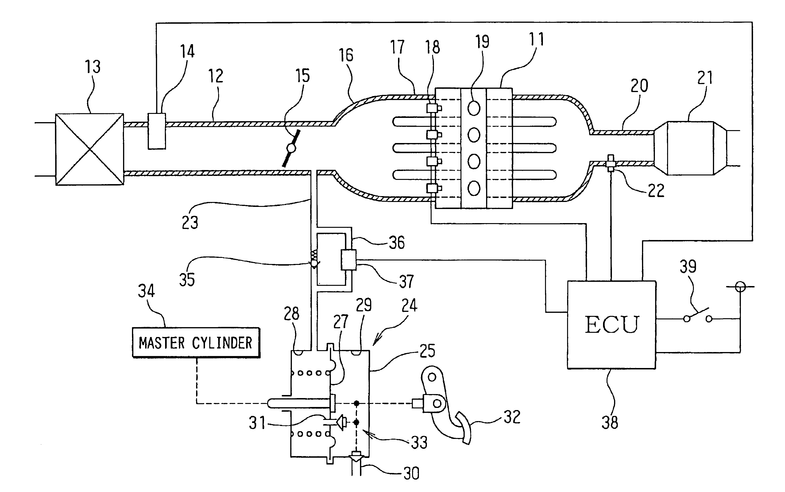
Referring to FIG. 1 and FIG. 2, a first embodiment of the invention is described herein after. FIG. 1 shows a schematic construction of an engine control system. At the most upstream of an intake pipe 12 of an internal combustion engine or an engine 11, an air cleaner 13 is disposed, downstream of which an airflow meter 14 is disposed for detecting an intake airflow. Downstream of the airflow meter 14, a throttle valve 15 is disposed, an opening of which is controlled by a DC motor or the like.

A surge tank 16 is disposed downstream of the throttle valve 15, which is provided with an intake manifold 17 for introducing the air into the individual cylinders of the engine 11. To the vicinities of the intake ports of the intake manifold 17 for the individual cylinders, fuel injection valves 18 are disposed individually. Ignition plugs 19 are provided in the cylinder head for the individual cylinders so that the air / fuel mixtures in the cylinders are ignited with the spa...

second embodiment

(Second Embodiment)

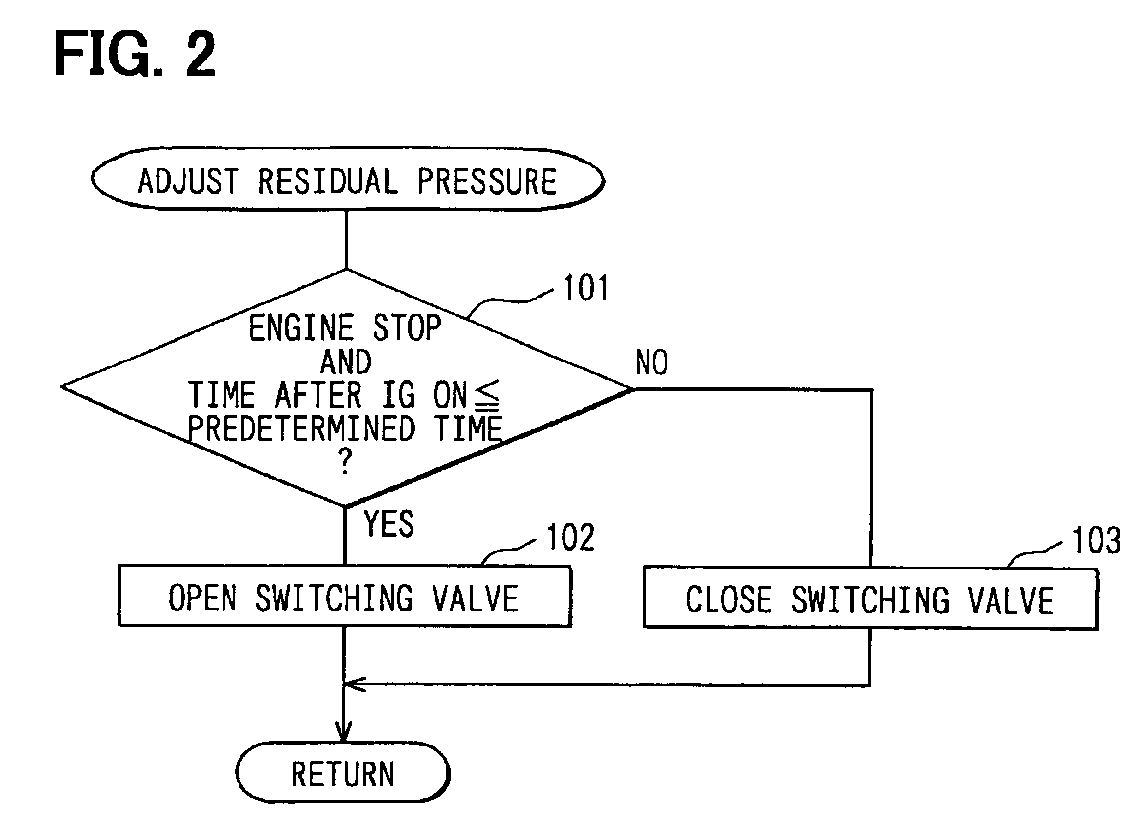
The switching valve 37 is disposed in the bypass passage 36 in the first embodiment. In second embodiment shown in FIG. 3, an orifice 40 is provided in place of the switching valve 37 in the bypass passage 36. The orifice 40 has a far smaller passage diameter than that of the remaining portion of the bypass passage 36. As a result, the airflow through the bypass passage 36 can be reduced to such a low rate as can be ignored while the engine is running. A bake booster residual pressure adjusting means is comprised of bypass passage 36 and orifice 40. The remaining system constructions are identical to those of the first embodiment.

The orifice 40 is disposed in the bypass passage 36. Therefore, the air in the intake pipe 12 can be gradually introduced into the brake booster 24 through the orifice 40 during the engine stop so that the residual pressure of the brake booster 24 can be set substantially to the atmospheric pressure (i.e., the pressure equal to the intake...

third embodiment

(Third Embodiment)

A third embodiment of the invention will be described with reference to FIG. 4 and FIG. 5. In the third embodiment as shown in Fig. a pressure sensor 41 (i.e., suction airflow information detecting means) is disposed between the check valve 35 and the brake booster 24 in the vacuum introducing passage 23. The pressure (corresponding to the residual pressure of the brake booster 24) in the vacuum introducing passage 23 is detected by that pressure sensor 41 thereby to detect the information on the airflow to be sucked from the brake booster 24 into the intake pipe 12 at the starting time. The remaining system constructions are identical to those of the first embodiment.

In the third embodiment, moreover, the starting time fuel injection rate setting program shown in FIG. 5 is executed. At the engine starting time, the airflow Q1 to be sucked from the brake booster 24 into the intake pipe 12 is calculated on the basis of the pressure (corresponding to the residual pre...


PUM


Abstract

A bypass passage for bypassing a check valve is connected with a vacuum introducing passage of a brake booster. The bypass passage is provided with a switching valve. Just before the start of an engine, the switching valve temporarily opens the bypass passage whereby to equalize a remaining pressure of the brake booster substantially becomes equal to an atmospheric level. As a result, the pressure in the brake booster at the starting time is set to substantially the atmospheric level so that the airflow to be sucked from the brake booster into the intake pipe at the starting time is made substantially contact every times. Thus, the fuel injection rate can be set considering the airflow to be sucked from the brake booster into the intake pipe at the starting time, even if that airflow cannot be detected.

Description

CROSS-REFERENCE TO RELATED APPLICATIONThis application is based on Japanese Patent Application No. 2003-144935 filed on May 22, 2003, the disclosure of which is incorporated herein by reference.FIELD OF THE INVENTIONThe present invention relates to a control system for an internal combustion engine, which has an airflow meter for measuring an amount of intake air and an intake pipe vacuum type break booster.BACKGROUND OF THE INVENTIONA conventional air / fuel control system for an internal combustion engine, as disclosed in JP-A-4-134159, is provided with an airflow meter in the intake pipe. A fuel injection amount is determined according to an amount of intake air measured by the airflow meter so that air / fuel ratio is controlled to predetermined value.JP-A-7-119511 shows a vehicle driven by an internal combustion engine, the vehicle having a vacuum type brake booster which utilizes an intake pipe vacuum (negative pressure) created downstream of a throttle valve. The intake pipe vacu...

Claims


Application Information

Patent Timeline
IPC IPC(8): B60T13/52F02D41/18F02D41/06F02N17/00F02N17/08B60T17/00F02D29/02F02D41/04F02N11/10F02N19/00
CPCB60T13/52F02D41/182F02D41/062F02N19/00
Inventor KAYAMA, RYOZOANNOURA, TOSHIKIHOSHI, KOICHIITOH, TAKAAKI
Owner DENSO CORP
Why Eureka
Try Eureka