Mold spraying system

a spraying system and mold technology, applied in the field of spraying systems, can solve the problems of molten metal material creeping into small defects in the mold, formation of flashes, defects in one or more subsequent molded parts, etc., and achieve the effect of maintaining the supply pressure of materials

Inactive Publication Date: 2005-02-22
HONDA MOTOR CO LTD
View PDF14 Cites 13 Cited by
  • Summary
  • Abstract
  • Description
  • Claims
  • Application Information

AI Technical Summary

Benefits of technology

The present invention is directed to a spraying system for spraying one or more materials onto a mold used for producing molded components. More specifically, the present invention comprises a system that can spray one or more materials onto a mold, such as a die-cast mold, while the mold is located in a molding machine running with a short cycle time, and wherein the supply pressure of the materials can be sufficiently maintained despite the high frequency of machine cycles.
In order for die-casting to be cost-effective, it is typically necessary that a large quantity of die-cast components be produced. In this manner, it is possible to spread out the cost of what is often a costly die-cast mold over a large number of components molded therefrom. To facilitate cost-effectiveness, it is also desirable that the die-casting machine used to produce the components be operated in the most efficient manner. Thus, the fastest molding cycle possible is usually sought out. To obtain a fast molding cycle, it is essential that part removal and any mold preparation, such as that previously discussed, be performed as quickly as possible. The requirement of haste, as well as safety, dictates that hand-cleaning of the mold halves and hand-application of a release agent and / or other substances thereto is not possible. As such, each of these processes is typically administered to by an automated device or devices.

Problems solved by technology

During the molding process, molten metal material may creep into small defects in the mold, or may partially invade the parting line that occurs between the flush-mating surfaces of the mold halves.
This may result in the formation of what is typically referred to as flash—thin areas of excess material that are often attached to a molded component.
Flash, or other contaminants that find their way onto the mold can cause defects in one or more subsequently molded parts, or may, if allowed to build up, prevent complete mating of the mold halves.
As it would not be practical to perform a hand-cleaning of die-cast molds between molding cycles, cleaning is typically accomplished using high-pressure air.
Due to the molten state of the metal used to form die-cast components, die-cast molds typically become extremely hot during the die-casting process.
The requirement of haste, as well as safety, dictates that hand-cleaning of the mold halves and hand-application of a release agent and / or other substances thereto is not possible.
However, these known devices had several undesirable characteristics, such as, for example, the residing thereof directly over the mold halves—which could allow for such a device to fall between the mold halves during certain portions of the molding cycle.

Method used


Image

  • Mold spraying system
  • Mold spraying system
  • Mold spraying system

Examples


Embodiment Construction

)

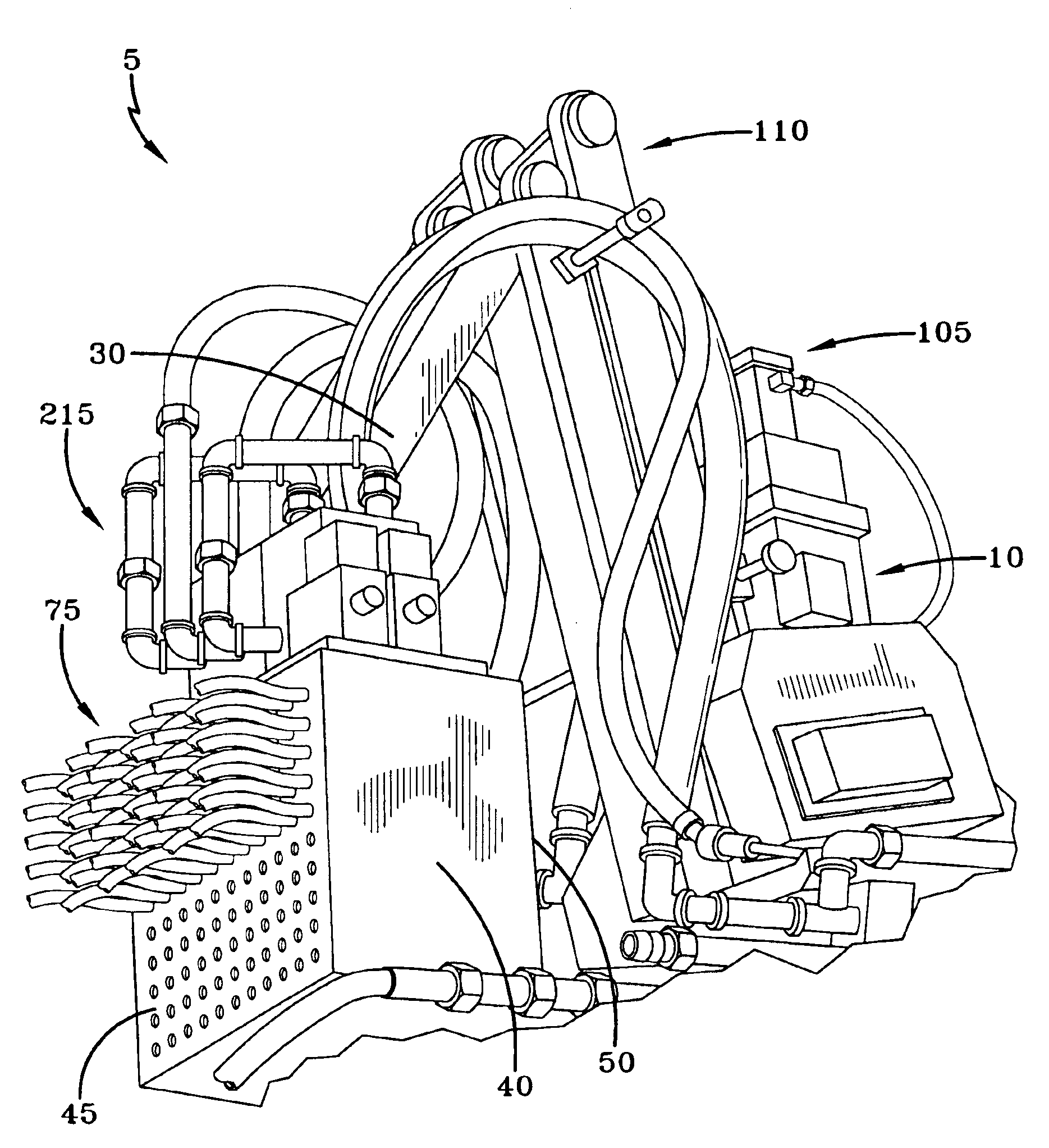
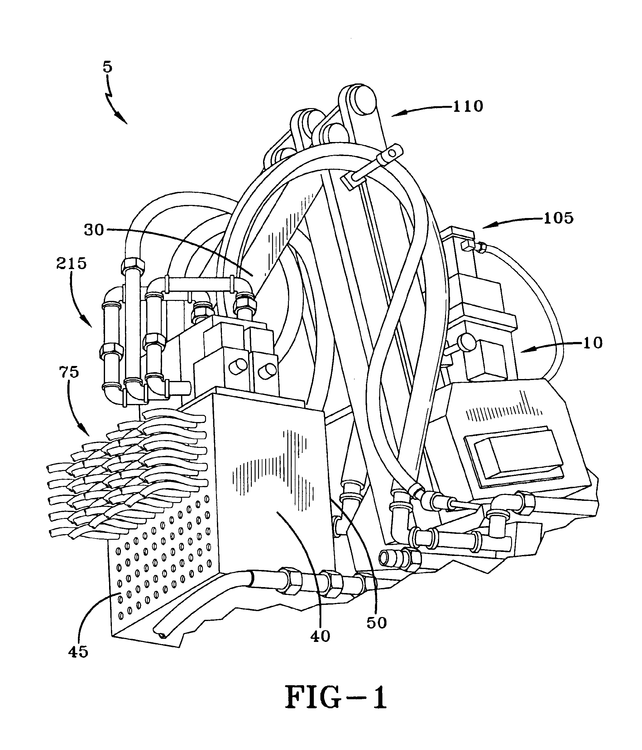
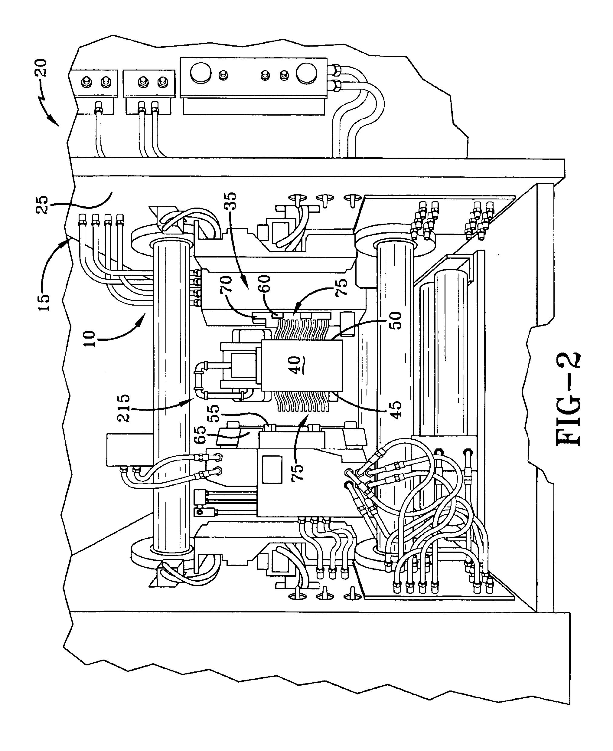
The present invention consists of a mold spraying system for use in a molding process, wherein the mold spraying system is able to provide an adequate spraying pressure to a spray head thereof despite system pressure losses, and despite a high frequency of spraying cycles. While it should be realized by one skilled in the art that the spraying system of the present invention may be applicable to a variety of molding processes, for purposes of illustration, and not limitation, the spraying system will be described below especially with respect to its use in a die-casting process. The embodiment of the spraying system of the present invention depicted in FIGS. 1-3 allows for the spraying of one or more materials onto the molding surfaces of a die-cast mold—while halves of the mold are separated during the molding cycle. The spraying system of the present invention further permits the materials to be sprayed onto the mold at an acceptable and substantially constant pressure, even when...


PUM

PropertyMeasurementUnit
pressureaaaaaaaaaa
speedaaaaaaaaaa
forceaaaaaaaaaa

Abstract

A mold spraying system for emitting one or more sprayable materials onto portions of a mold, such as a die-cast mold, while the mold is located in a molding machine. The spraying system has an emitter, such as a spray head, for directing the one or more materials onto portions of each half of the mold when the mold is in an opened position between molding cycles of the molding machine. The spray head is connected to a manipulator for positioning the spray head between the mold halves. A pressure boosting unit is employed to ensure that the sprayable materials are supplied to the spray head at a sufficient pressure, notwithstanding any system pressure losses and / or the high frequency of spraying operations required to be performed as a result of a short molding machine cycle.

Description

BACKGROUND AND SUMMARY OF THE INVENTIONThe present invention is directed to a spraying system for spraying one or more materials onto a mold used for producing molded components. More specifically, the present invention comprises a system that can spray one or more materials onto a mold, such as a die-cast mold, while the mold is located in a molding machine running with a short cycle time, and wherein the supply pressure of the materials can be sufficiently maintained despite the high frequency of machine cycles.While the spraying system of the present invention may be applicable to a variety of molding processes, for purposes of simplicity and clarity, the spraying system will be described below only with respect to its use in a die-casting process. Die-casting is a well known process whereby metallic components can be quickly and accurately molded from a molten metal. Metals commonly employed in die-casting operations may include, for example, aluminum, zinc, brass and magnesium....

Claims


Application Information

Patent Timeline
Patent Type & Authority Patents(United States)
IPC IPC(8): B05B15/00B05B15/10B05B7/24B22D17/20B05B1/14B05B1/00
CPCB22D17/2007B05B15/10B05B7/2489B05B1/005B05B1/14B05B15/72
Inventor JORDAN, TODDKAGESHITA, TAMOTSUNISHIO, KAZUOQUEEN, BOB
Owner HONDA MOTOR CO LTD
Why Eureka
Try Eureka