System and method for detecting rotating stall in a centrifugal compressor

a centrifugal compressor and detection system technology, applied in the direction of machines/engines, engine starters, liquid fuel engines, etc., can solve the problems of affecting the performance of the compressor and/or system, complicated computations are performed to determine, and affect the overall sound and vibration level of the system. , to achieve the effect of reducing or eliminating the noise of the rotating stall

Active Publication Date: 2005-02-22
JOHNSON CONTROLS TYCO IP HLDG LLP
View PDF34 Cites 44 Cited by
  • Summary
  • Abstract
  • Description
  • Claims
  • Application Information

AI Technical Summary

Benefits of technology

One advantage of the present invention is that it uses a simplified package of electronics and hardware to detect rotating stall in the diffuser portion of the compressor.
Another advantage of the present invention is that the determination of rotating stall can be used to make decisions on possible techniques to reduce or el

Problems solved by technology

In both cases, the presence of rotating stall can adversely affect performance of the compressor and/or system.
However, impeller rotating stall is typically of greater interest because it can affect impeller reliability, especially in axial flow compressors such as aircraft engines, while diffuser rotating stall typically impacts the overall sound and vibration levels of a system.
Often, very complicated computations are performed to determine precursors to the onset of impeller rotating stall.
One drawback of this technique is that it is only for the detection of impeller rotating stall in an axial flow compressor and does not discuss diffuser rotating stal

Method used


Image

  • System and method for detecting rotating stall in a centrifugal compressor
  • System and method for detecting rotating stall in a centrifugal compressor
  • System and method for detecting rotating stall in a centrifugal compressor

Examples


Embodiment Construction

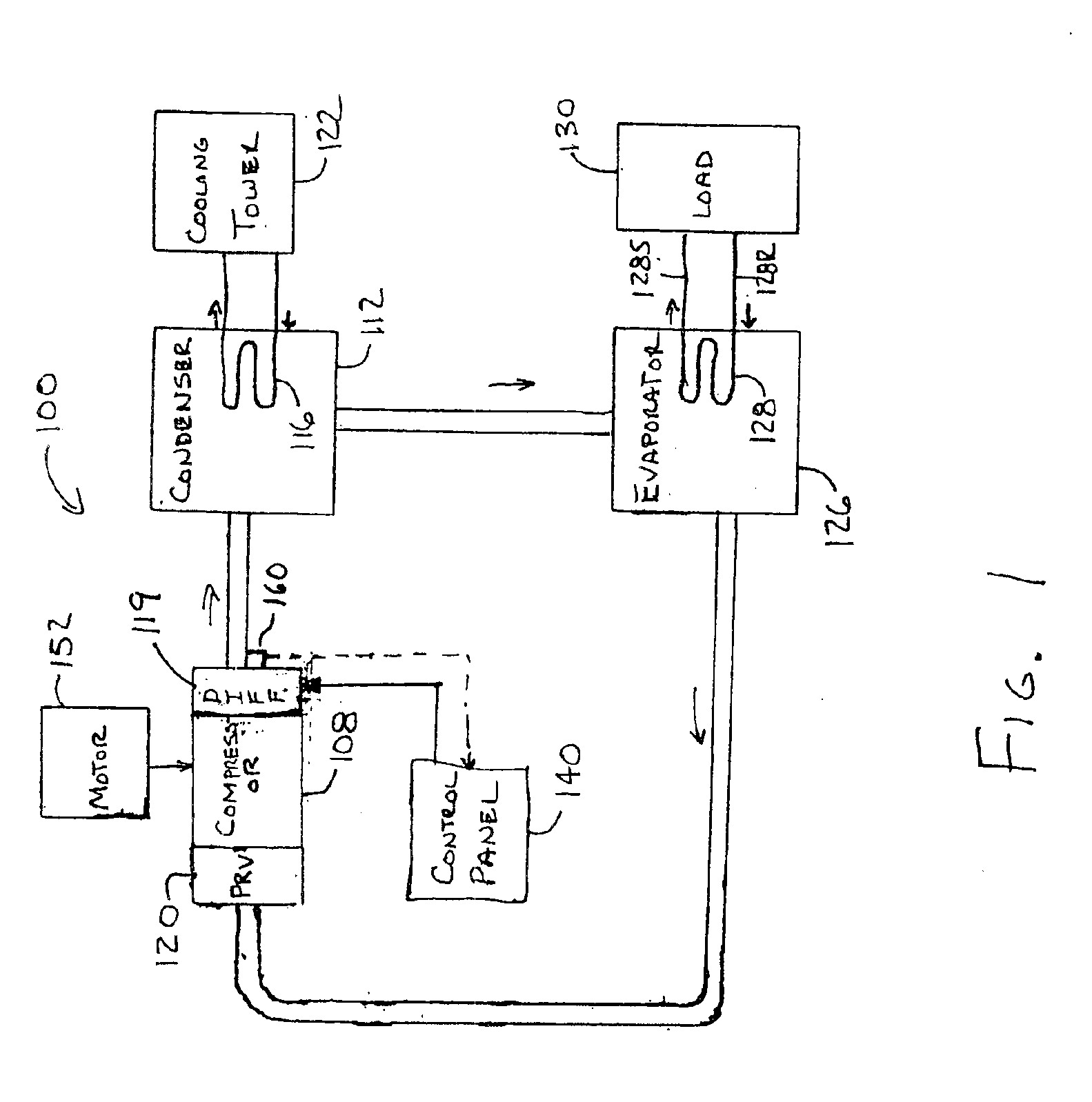
A general system to which the invention can be applied is illustrated, by means of example, in FIG. 1. As shown, the HVAC, refrigeration or liquid chiller system 100 includes a compressor 108, a condenser 112, a water chiller or evaporator 126, and a control panel 140. The control panel140 receives input signals from the system 100 that indicate the performance of the system 100 and transmits signals to components of the system 100 to control the operation of the system 100. The conventional liquid chiller system 100 includes many other features that are not shown in FIG. 1. These features have been purposely omitted to simplify the drawing for ease of illustration.

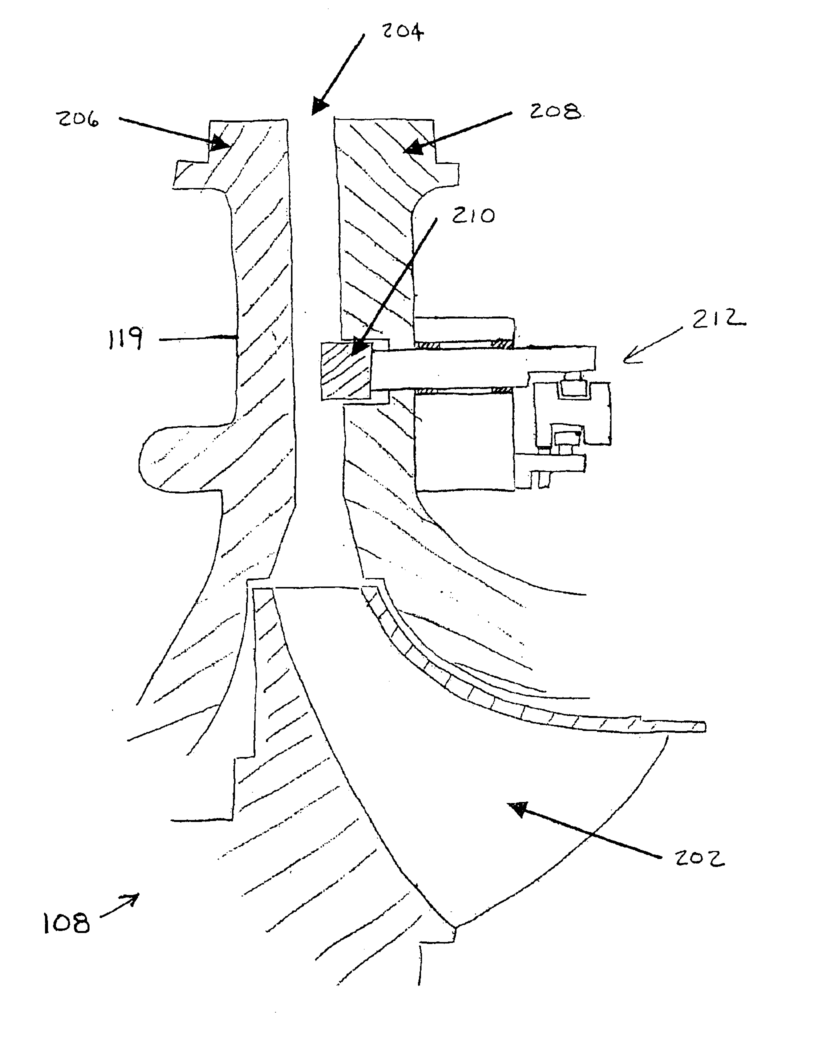
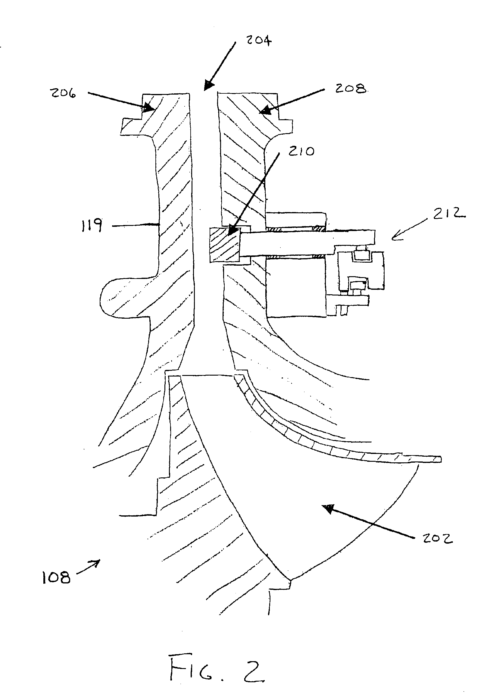
Compressor 108 compresses a refrigerant vapor and delivers the vapor to the condenser 112 through a discharge line. The compressor 108 is preferably a centrifugal compressor; however, the present invention can be used with any type of compressor that can experience a rotating stall condition or operate at a flow where rot...


PUM


Abstract

A system and method is provided for detecting and controlling rotating stall in the diffuser region of a centrifugal compressor. The process begins with the detection or sensing of acoustic energy associated with the onset of rotating stall. A pressure transducer is placed in the gas flow path downstream of the impeller, preferably in the compressor discharge passage or the diffuser, to measure the sound or acoustic pressure phenomenon. Next, the signal from the pressure transducer is processed either using analog or digital techniques to determine the presence of rotating stall. Rotating stall is detected by comparing the detected energy amount, which detected energy amount is based on the measured acoustic pressure, with a predetermined threshold amount corresponding to the presence of rotating stall. Finally, an appropriate corrective action is taken to change the operation of the centrifugal compressor in response to the detection of rotating stall.

Description

BACKGROUND OF THE INVENTIONThe present invention relates generally to the detection of rotating stall in a centrifugal compressor. More specifically, the present invention relates to systems and methods of detecting rotating stall in the diffuser portion of a centrifugal compressor by sensing acoustic energy changes in the discharge from the compressor.Rotating stall in a centrifugal compressor can occur in the rotating impeller or rotor of the compressor or in the stationary diffuser of the compressor downstream from the impeller. The frequencies of the energy associated with rotating stall are typically within a common range of values whether the rotating stall is occurring in the impeller region (impeller rotating stall) or in the diffuser region (diffuser rotating stall). In both cases, the presence of rotating stall can adversely affect performance of the compressor and / or system. However, impeller rotating stall is typically of greater interest because it can affect impeller r...

Claims


Application Information

Patent Timeline
IPC IPC(8): F04D27/02
CPCF04D27/02Y10S415/914F04D27/001F04D27/0253F04D29/464F05D2250/52F04D15/00F04D27/00
Inventor STABLEY, ROBERT EDWARDBEAVERSON, GREGORY KEITHBENDER, JAMES EDWIN
Owner JOHNSON CONTROLS TYCO IP HLDG LLP
Why Eureka
Try Eureka