Method of forming phosphor layer of gas discharge tube

a technology of gas discharge tube and fluorescence layer, which is applied in the direction of luminescence, lighting and heating apparatus, and application of luminescent coatings, etc., can solve the problems of reducing light emission efficiency, less improvement of discharge characteristics, and rapid degradation of phosphors by discharge, so as to prolong the life of display devices, increase light emission efficiency, and enhance image quality

Inactive Publication Date: 2005-02-22
SHINODA PLASMA
View PDF2 Cites 43 Cited by
  • Summary
  • Abstract
  • Description
  • Claims
  • Application Information

AI Technical Summary

Benefits of technology

In consideration of such circumstances, it is an object of the present invention to form a phosphor layer partially on the internal surface of an elongated gas discharge tube, thereby increasing the light emission efficiency, enhancing quality of images and prolonging the lifetime of a display device using the gas discharge tube.
According to the present invention, the phosphor powder and the binding resin are deposited on one side of the internal surface of the elongated tubular vessel to be the gas discharge tube, that is, a bottom surface of the tubular vessel in a sideways state and are burnt to form the phosphor layer. Consequently, it is possible to form a vacancy having no phosphor layer on the internal surface of the gas discharge tube. By forming an electrode on the vacancy, the lifetime of the phosphor layer can be increased.

Problems solved by technology

If the phosphor layers are thus present on the discharge electrodes, the phosphors are rapidly deteriorated by the discharge.
Therefore, discharge characteristics are less improved and a light emission efficiency is reduced.
Therefore, the efficiency of taking out emitted light toward a front surface of a screen is poor.
Moreover, the expansion of discharge causes apparent expansion of pixels, which affects adjacent pixels and consequently deteriorates quality of images.
Furthermore, there is a problem in that a discharge interference is caused between adjacent pixels.
However, it is hard to form the phosphor layer partially on the internal surface of an elongated gas discharge tube having a diameter of 2 mm or less and a length of 300 mm or more.

Method used


Image

  • Method of forming phosphor layer of gas discharge tube
  • Method of forming phosphor layer of gas discharge tube
  • Method of forming phosphor layer of gas discharge tube

Examples


example

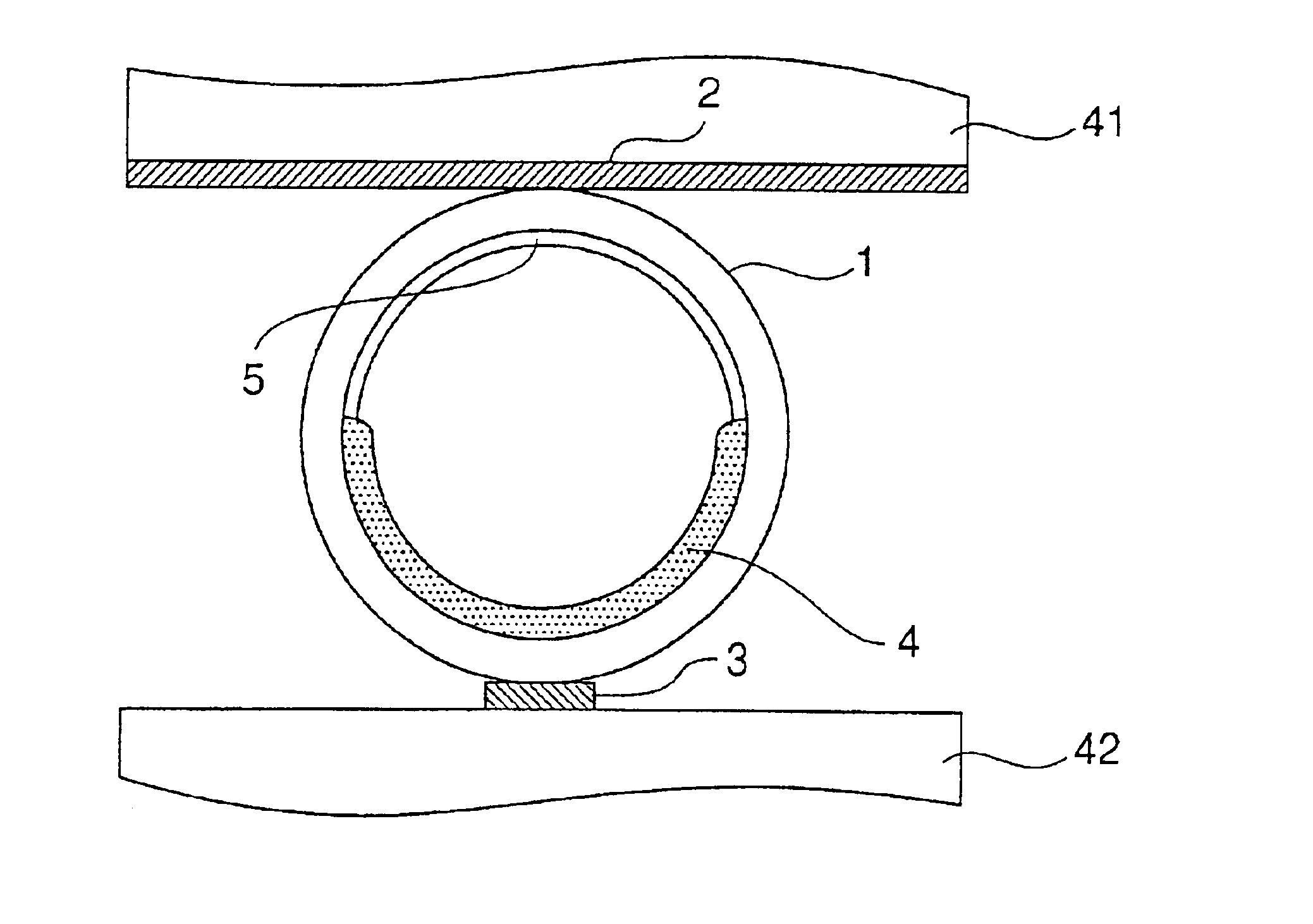
In the present example, the phosphor layer shown in FIG. 3 and FIGS. 4(a) and 4(b) was formed. First of all, 16 parts of phosphor powder, 2 parts of polyvinyl alcohol (a mean degree of polymerization of 2800), 6 parts of pure water, 23 parts of acetone and 53 parts of 1,3-dimethyl-2-imidazolidinone were used for the phosphor slurry.

The phosphor slurry was introduced into a tubular vessel formed of borosilicate glass having an outside diameter of 1 mm and an inside diameter of 0.8 mm in which MgO is uniformly formed on an internal wall surface. In the introduction, a solution (a low-viscosity solvent) containing 23 parts of acetone and 23 parts of 1,3-dimethyl-2-imidazolidinone was added to a solution containing 16 parts of phosphor powder, 2 parts of polyvinyl alcohol (a binding resin), 6 parts of pure water and 30 parts of 1,3-dimethyl-2-imidazolidinone immediately before the introduction. The tubular vessel is stationarily put horizontally in a sideways state so that the phosphor ...


PUM

PropertyMeasurementUnit
diameteraaaaaaaaaa
lengthaaaaaaaaaa
diameteraaaaaaaaaa

Abstract

A method of forming a phosphor layer of a gas discharge tube provided with the phosphor layer on an internal surface of an elongated tubular vessel forming a discharge space. The method includes the steps of introducing a slurry of phosphor powder and a binding resin dispersed in a medium into the tubular vessel, holding the tubular vessel sideways to deposit the phosphor powder and the binding resin in the tubular vessel, and removing the medium from the tubular vessel, thereby forming a phosphor layer on one side of the internal surface of the tubular vessel.

Description

CROSS-REFERENCE TO RELATED APPLICATIONThis application is related to Japanese application No. 2001-276962 filed on Sep. 12, 2001, whose priority is claimed under 35 USC § 119, the disclosure of which is incorporated by reference in its entirety.BACKGROUND OF THE INVENTION1. Field of the InventionThe present invention relates to a method of forming a phosphor (fluorescent) layer of a gas discharge tube, and more particularly to a method of forming a phosphor layer of an elongated gas discharge tube having a diameter of approximately 0.5 to 5 mm.2. Description of the Related ArtIn a gas discharge tube such as a conventional fluorescent lamp, a phosphor layer is formed on an internal surface of the gas discharge tube by coating the internal surface of the gas discharge tube with a phosphor slurry (a coating liquid containing phosphor powder) and then drying and burning. Accordingly, the phosphor layer is uniformly formed on the internal surface of the tube. For this reason, light is em...

Claims


Application Information

Patent Timeline
Patent Type & Authority Patents(United States)
IPC IPC(8): H01J9/22H01J11/00H01J9/227H01J9/00H01J11/12H01J11/18H01J11/24H01J11/26H01J11/42H01J61/42H01J61/44H01J61/46
CPCH01J9/223H01J61/46H01J61/44H01J61/42
Inventor YAMADA, HITOSHITOKAI, AKIRAISHIMOTO, MANABUSHINODA, TSUTAE
Owner SHINODA PLASMA
Why Eureka
Try Eureka