Ultrasonic angioscope system

an angioscope and ultrasonic technology, applied in the field of ultrasonic angioscope systems, can solve the problems of not obtaining ahead information, conventional ultrasonic angioscopes have a problem to obtain only two-dimensional information of the cross section of the blood vessel, and it takes a long time for obtaining three-dimensional images with ultrasonic angioscopes, etc., to achieve the effect of higher reception sensitivity

Inactive Publication Date: 2005-02-22
NARA INSTITUTE OF SCIENCE AND TECHNOLOGY
View PDF6 Cites 38 Cited by
  • Summary
  • Abstract
  • Description
  • Claims
  • Application Information

AI Technical Summary

Problems solved by technology

However, the ultrasonic angioscopes takes a long time for obtaining a three-dimensional image and does not obtain ahead information of the stricture portion because there is no method for generating the ultrasonic waves having no directivity.
However, the conventional ultrasonic angioscopes have a problem to obtain only two-dimensional information of the cross section of the blood vessel.

Method used


Image

  • Ultrasonic angioscope system
  • Ultrasonic angioscope system
  • Ultrasonic angioscope system

Examples


Embodiment Construction

Hereinbelow, an embodiment of the present invention will be described in detail with reference to the drawings.

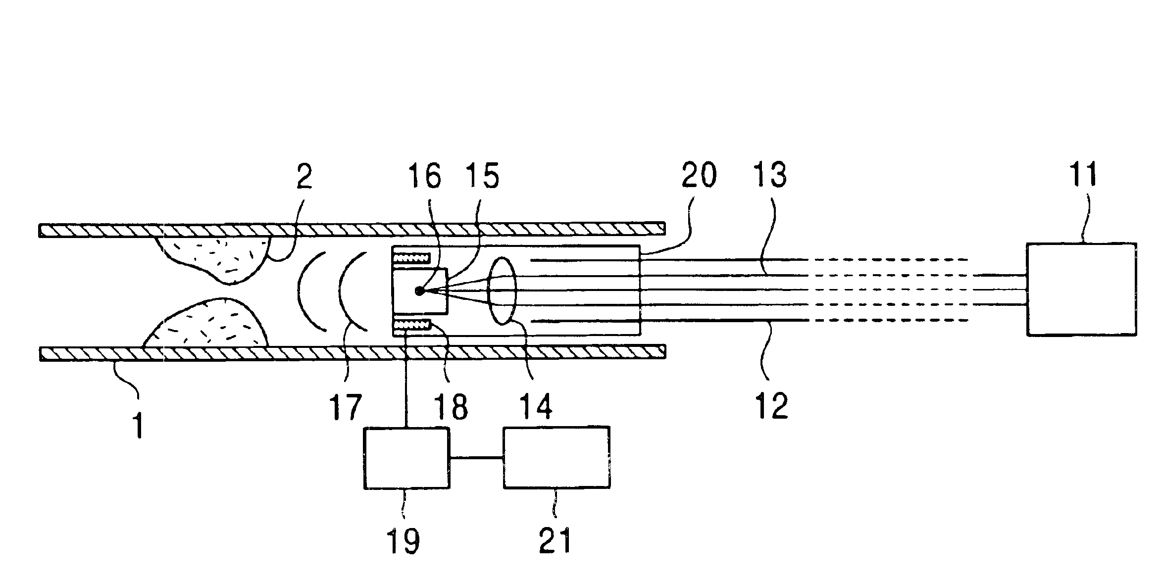
FIG. 1 is a schematic diagram showing an ultrasonic angioscope system using a laser breakdown according to an embodiment of the present invention.

Referring to FIG. 1, reference numeral 1 denotes a blood vessel. Reference numeral 2 denotes a stricture portion of the blood vessel 1. Reference numeral 11 denotes a laser generating device installed outside the human body. Reference numeral 12 denotes an optical fiber. Reference numeral 13 denotes laser beams emitted from the laser generating device 11. The laser beams 13 generated by the laser generating device 11 installed outside the human body pass through the blood vessel 1 by using the optical fiber 12 and are introduced to a desired portion. Reference numeral 14 denotes a lens for condensing the laser beams 13. Reference numeral 15 denotes a water tank as a dielectric effected by the condensed laser beams. The laser beams...


PUM


Abstract

An ultrasonic angioscope system which uses an imaging technique of sending ultrasonic waves to a portion ahead of a stricture of a blood vessel and visualizing a portion in the forward direction of the angioscope, and which uses a laser breakdown is provided. The ultrasonic angioscope system includes: a laser generating device (11) installed outside the human body; a probe (20) that introduces laser beams (13) emitted from the laser generating device (11) into a blood vessel (1) via an optical fiber (12), is set at the tip of the optical fiber (12), and has a lens (14) and a water tank (15) as a dielectric; ultrasonic-wave generating means that uses a laser breakdown (16) produced in the water tank (15); a plurality of hydrophones (18) that receive reflected waves, of ultrasonic waves emitted by the laser breakdown (16), from a stricture portion (2) of a blood vessel (1), and are disposed at the tip end of the probe (20); and means of forming a stricture-shaped image of the stricture portion (2) based on the signals received from the hydrophones (18) by a synthetic aperture method.

Description

TECHNICAL FIELDThe present invention relates to an ultrasonic angioscope system for visualizing a blood vessel in which a stricture portion is caused by using ultrasonic waves generated by the condense of lasers and the occurrence of a laser breakdown.BACKGROUND ARTConventionally, technologies in the above-mentioned field are disclosed as follows. That is,(1) “Handbook of medical ultrasonic devices” edited by Japan Electronic Industry published by CORONA PUBLISHING Co., Ltd. on Jan. 20, 1997, and(2) Japanese Unexamined Patent Application Publication No. 11-128229.The conventional ultrasonic angioscope systems obtain the cross section of the blood vessel by scanning beam ultrasonic waves in the circumferential direction.Hereinbelow, the above conventional ultrasonic angioscope systems are described in detail.Treatments for a stricture portion of the blood vessel use a method for penetrating the lesion by penetrating a guide wiring in the blood vessel and by using a balloon inserted i...

Claims


Application Information

Patent Timeline
Patent Type & Authority Patents(United States)
IPC IPC(8): A61B5/026A61B8/06A61B8/12
CPCA61B5/0261A61B8/12A61B8/06A61B5/0263
Inventor KAWATA, SATOSHISUGIURA, TADAOOHSHIRO, OSAMUCHIHARA, KUNIHIRO
Owner NARA INSTITUTE OF SCIENCE AND TECHNOLOGY
Why Eureka
Try Eureka