Method and device for transmitting force magnetically
- Summary
- Abstract
- Description
- Claims
- Application Information
AI Technical Summary
Benefits of technology
Problems solved by technology
Method used
Image
Examples
first embodiment
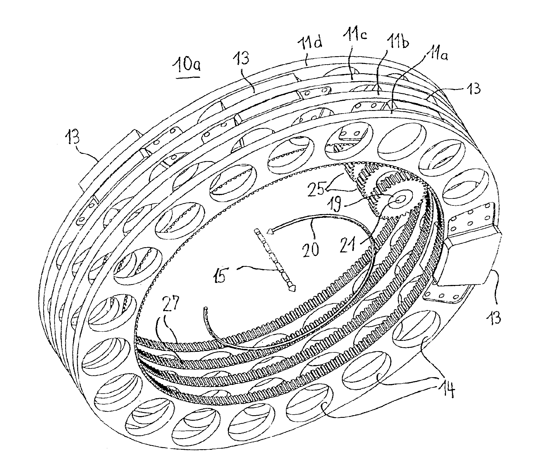
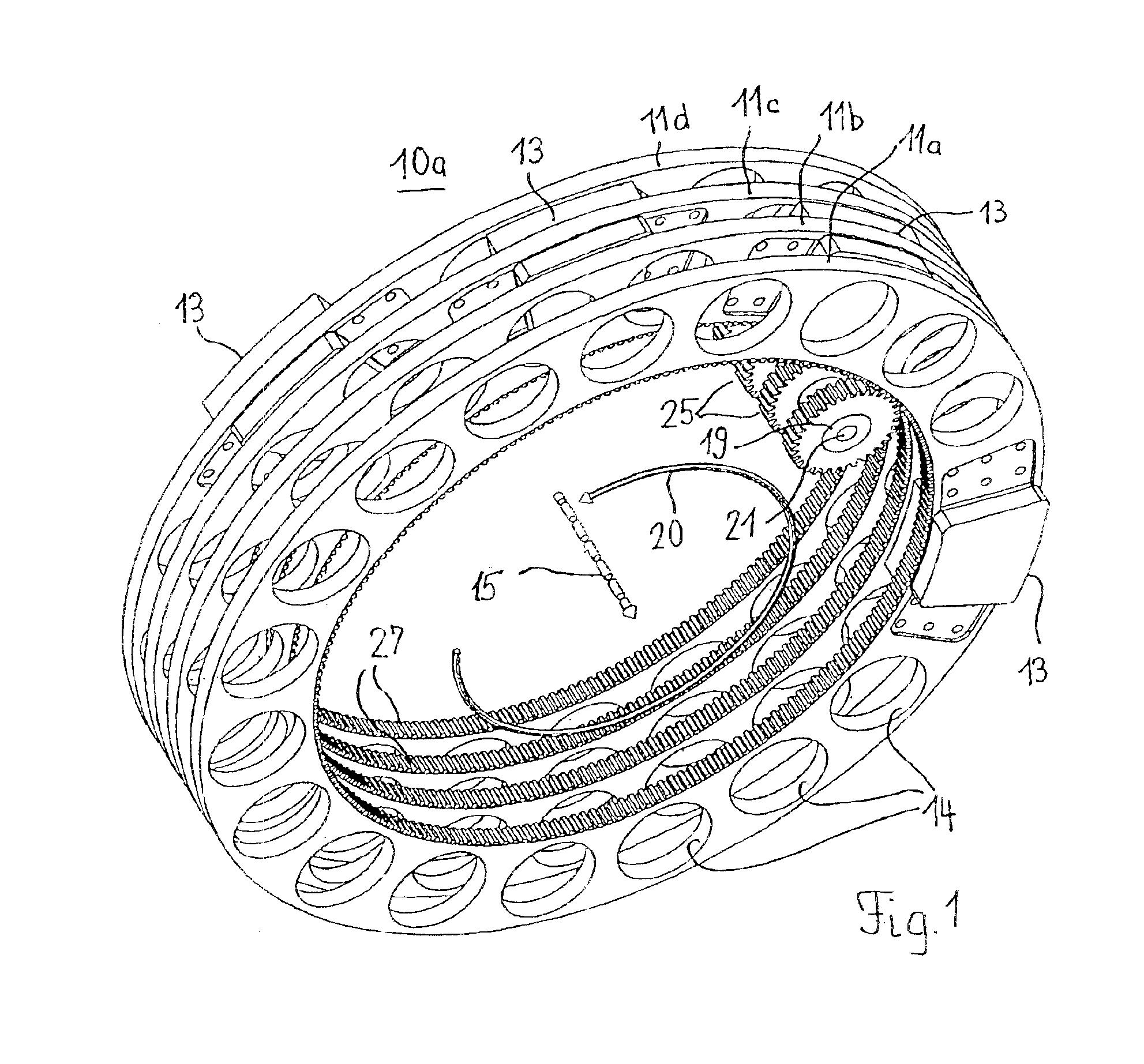
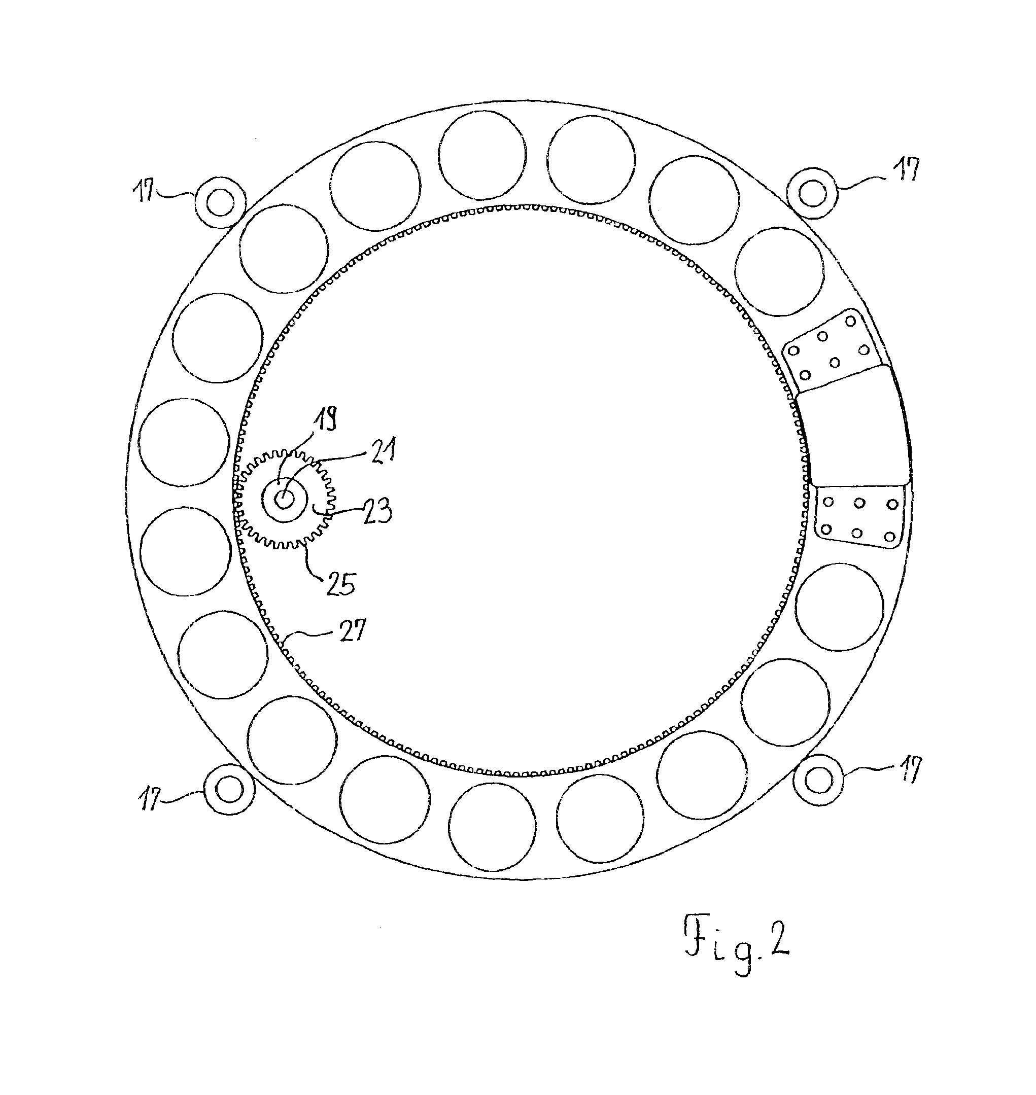
FIGS. 1 to 4 show a device 10a according to the invention for transmitting force magnetically which is formed by a plurality of rings 11a, 11b, 11c, etc. which are spaced apart from one another and are fitted for magnets 13. The rings 11a, 11b, 11c etc. act as supports for the magnets 13 and are free to rotate about a common axis 15. Positioned around the peripheries of rings 11a, 11b, 11c, etc. at regular intervals are bearings 17 (not shown in FIG. 1) which ensure that the rings are free to rotate with the absolute minimum of frictional losses.
Each ring 11a, 11b, 11c, etc. is fitted with at least one magnet 13. At least part of the magnet or magnets is held in recesses 14a in ring 11. The magnets 13, which are used to transmit force from ring to ring, are orientated in the same direction on the rings, which are arranged one behind the other, so that poles magnetised in that same way encounter one another when the rings rotate relative to one another. This arrangement for the magne...
second embodiment
FIGS. 4 and 5 show ring 11′ for use in a force-transmitting device according to the invention. Ring 11 differs from the embodiment shown in FIGS. 1 to 4 chiefly in that two magnets 13 situated diametrically opposite one another are arranged on ring 11. The magnets 13, which are rectangular in plan, are partly held on ring 11 in corresponding recesses and are arranged to be orientated in the same way (arrow 32=direction of polarisation). To make the magnetic field as strong as possible, the magnets 13 are preferably assembled into a stack from a plurality of individual magnets 13a, 13b, 13c (see FIG. 5). Each stack of magnets is held together by cups 29 which are secured to opposite sides of ring 11 by rivets 31. It goes without saying that the stacks of magnets can be fastened in place by any suitable means familiar to the person skilled in the art.
The ring 11″ shown in FIGS. 6 to 8, which has a total of four recesses 14b, can be used to allow force to be tapped off from the ring ar...
PUM
 Abstract
Description
Claims
Application Information
 - R&D
- Intellectual Property
- Life Sciences
- Materials
- Tech Scout
- Unparalleled Data Quality
- Higher Quality Content
- 60% Fewer Hallucinations
Browse by: Latest US Patents, China's latest patents, Technical Efficacy Thesaurus, Application Domain, Technology Topic, Popular Technical Reports.
© 2025 PatSnap. All rights reserved.Legal|Privacy policy|Modern Slavery Act Transparency Statement|Sitemap|About US| Contact US: help@patsnap.com


