Programmable precision current controlling apparatus

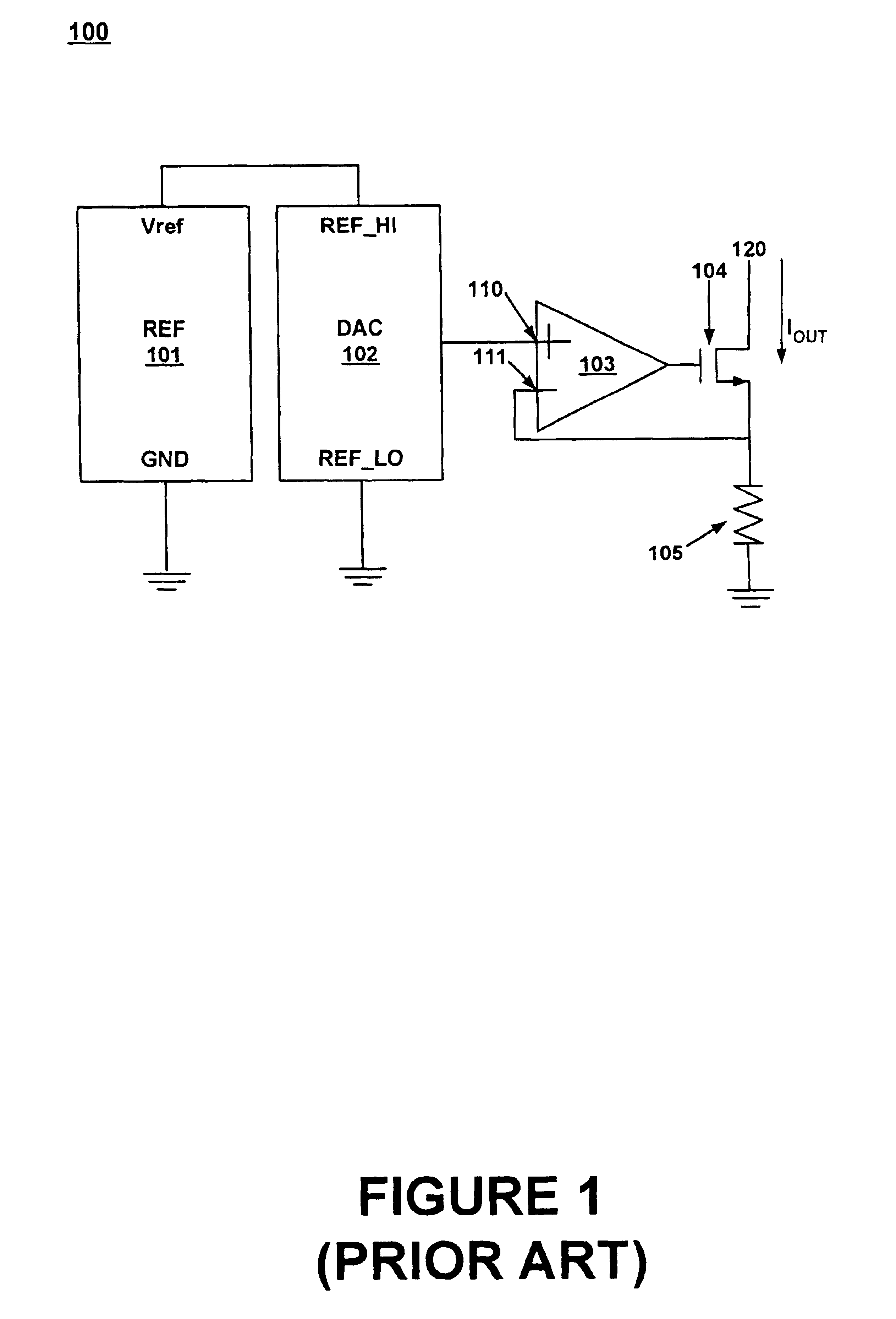
a current control and precision technology, applied in the direction of digital-analog convertors, transmission systems, instruments, etc., can solve the problems of b>100/b> being the limitation of output voltage as described above, and the manufacturing defects of semiconductor fabrication processes can be detected, so as to reduce the possibility of error sources, reduce the number of parts, and improve the accuracy

Inactive Publication Date: 2005-02-22
ADVANTEST CORP
View PDF6 Cites 16 Cited by
  • Summary
  • Abstract
  • Description
  • Claims
  • Application Information

AI Technical Summary

Benefits of technology

Embodiments of the present invention can be configured as a current source, a current sink, a current sink / source, a precision current sink / source with adjustable range, and an adaptive range precision current sink / source. The present invention reduces possible error sources by reducing the part count and makes use of the full dynamic range of the Digital to Analog Converter (DAC) by shifting its reference voltage as the output voltage varies.
More specifically, the proposed current source implementation makes use of the full scale range of the DAC and has no implicit limitations on the output voltage. It has fewer parts than prior art implementations and is therefore more accurate since it has fewer possible sources of error. Since fewer parts are utilized, the embodiments of the present invention are more cost effective. Embodiments of the present invention are especially cost effective in ATE systems, for example, where a large number of precision measurement units are required which necessitates a large number of precision programmable current sources as well. Thus, even a small cost savings per unit can be multiplied into large cost savings per system.

Problems solved by technology

Specifically, it has been known that manufacturing defects in the semiconductor fabrication process can be detected by precise measurement of current.
Current sinks of the types just described have had several problems and limitations associated with their use.
For example, one drawback of system 100 is the limitation on output voltage as described above.
However, this results in a reduction in resolution for this type of current sink.
Since errors due to noise, offset, and drift essentially stay the same, they may become significant in comparison to the desired output voltage.
Thus the ability of the prior art as shown in current sink 100 to precisely control current is limited in applications requiring low output voltage.
While this can effectively limit the voltage output from DAC 102, it also reduces the dynamic range of the DAC and limits the ability to precisely control current in some applications.
One drawback to the current source design of FIG. 3 is that the current range desired by entering the highest values of binary code to the DAC may be unreachable.
In addition, another problem of the prior art is that to provide both current sink and current source capability, DAC 403 must provide both positive voltage when acting as a current source and a negative voltage when acting as a current sink or vice versa.
Each programming bit of the DAC 403 now controls twice as much voltage, thus further aggravating the loss of resolution due to the unavailability of the highest order bits and reducing the precision with which current can be controlled.
Alternatively, to realize the same level of precision as the current sink of FIG. 1, 2 DACs or a 2 output DAC (e.g., DAC 403 of FIG. 4) are needed, thus increasing the cost of the circuit.
However, the use of the programming bits available to the DAC is still limited which results in a reduction in resolution for this type of current sink / source.
The higher part count also makes current sink / source 500 more expensive and more complex for manufacturers to fabricate.

Method used


Image

  • Programmable precision current controlling apparatus
  • Programmable precision current controlling apparatus
  • Programmable precision current controlling apparatus

Examples


Embodiment Construction

Reference will now be made in detail to embodiments of the present invention, examples of which are illustrated in the accompanying drawings. While the present invention will be described in conjunction with the following embodiments, it will be understood that they are not intended to limit the present invention to these embodiments alone. On the contrary, the present invention is intended to cover alternatives, modifications, and equivalents which may be included within the spirit and scope of the present invention as defined by the appended claims. Furthermore, in the following detailed description of the present invention, numerous specific details are set forth in order to provide a thorough understanding of the present invention. However, embodiments of the present invention may be practiced without these specific details. In other instances, well-known methods, procedures, components, and circuits have not been described in detail so as not to unnecessarily obscure aspects of...


PUM


Abstract

The present invention is a circuit for controlling current. In one embodiment, the high reference voltage input of a digital to analog converter is coupled with a reference voltage source which provides a positive reference voltage. A resistive load is coupled to an output of the digital to analog converter and to a circuit output pin. A sensing device couples the circuit output pin with the low reference voltage input of the digital to analog converter and to a reference ground input of the voltage source. The positive reference voltage, low reference voltage, and reference ground voltage are changed in response to the sensing device detecting a change in the output voltage.

Description

FIELD OF THE INVENTIONThe present invention relates to the field of current sink and current source circuits. More specifically, embodiments of the present invention are directed to precision programmable current controlling devices.BACKGROUND OF THE INVENTIONProgrammable current sources are some of the most versatile components used in analog technology. They can be used in a variety of applications including analog computation, offset cancellation, parameter adjustment measurements, characterization of devices, driving actuators, and in Automatic Test Equipment (ATE).In ATE applications, precise programmable current sources are necessary for precision parametric measurement units and integrated circuit quiescent current (IDDQ) measurements. The operating parameters in these applications necessitate precise current control, because the ATE system may be used as the reference for testing integrated circuits (ICs). Specifically, it has been known that manufacturing defects in the sem...

Claims


Application Information

Patent Timeline
Patent Type & Authority Patents(United States)
IPC IPC(8): G05F1/10G05F1/56
CPCG05F1/56
Inventor GUNTHER, ANDRE
Owner ADVANTEST CORP
Why Eureka
Try Eureka