Optical-element mountings exhibiting reduced deformation of optical elements held thereby

a technology of optical elements and mountings, applied in the field of optical element mountings, can solve the problems of unsatisfactory performance of conventional mountings of optical elements in these respects, and achieve the effect of optimal performan

Inactive Publication Date: 2005-02-22
NIKON CORP +1
View PDF9 Cites 40 Cited by
  • Summary
  • Abstract
  • Description
  • Claims
  • Application Information

AI Technical Summary

Benefits of technology

The needs summarized above are addressed by various aspects of the invention, wherein, inter alia, optical-element mountings are provided that prevent deformational and positional changes of respective optical elemen

Problems solved by technology

Unfortunately, conventional mountings for optical elements do not exhibit satisfactory performance in these regards, especially

Method used


Image

  • Optical-element mountings exhibiting reduced deformation of optical elements held thereby
  • Optical-element mountings exhibiting reduced deformation of optical elements held thereby
  • Optical-element mountings exhibiting reduced deformation of optical elements held thereby

Examples


first representative embodiment

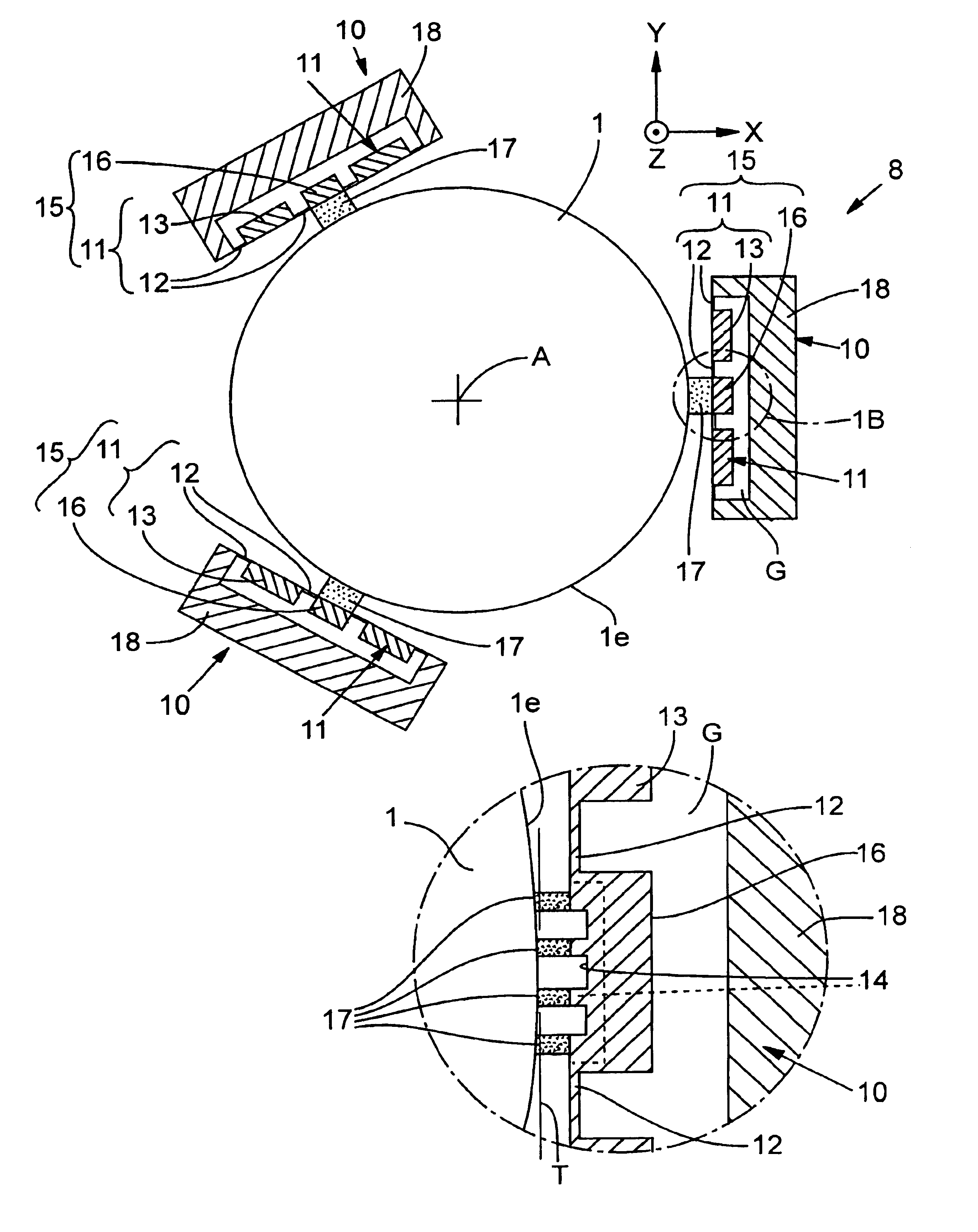
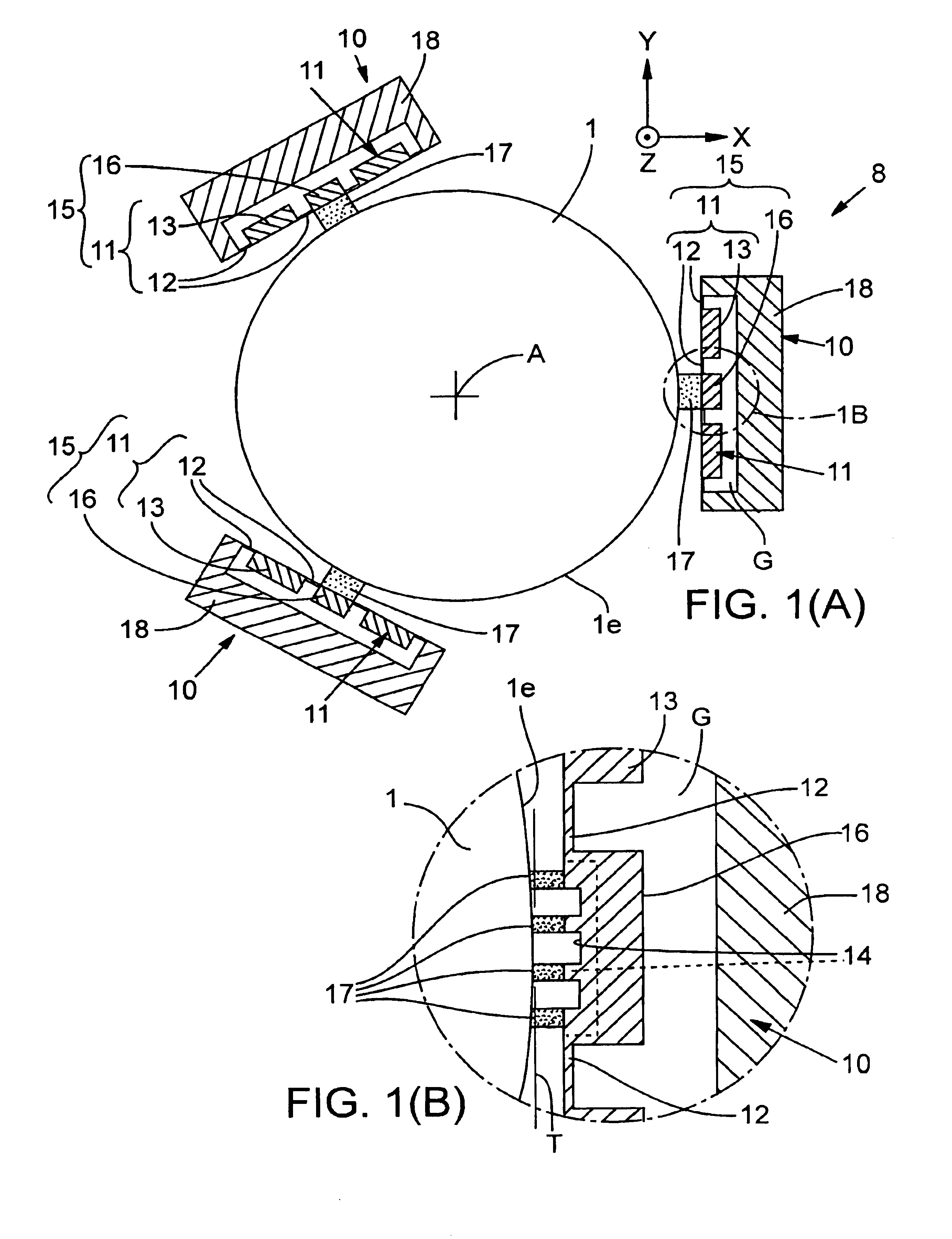
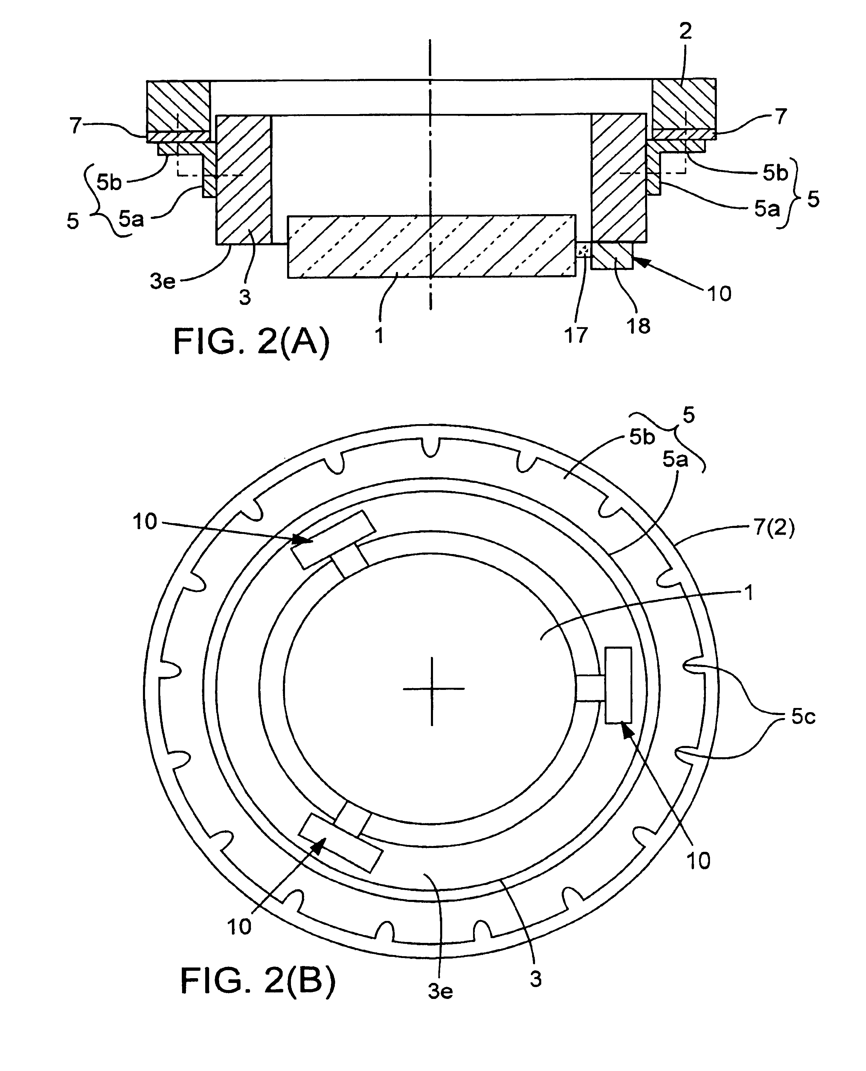
An optical-element mounting according to this representative embodiment is depicted in FIGS. 1(A)-1(B) and 2(A)-2(B), in which the depicted optical element is, by way of example, a plate-shaped mirror 1. The mirror 1 is shown as it would be mounted within an optical column (not shown) of an optical system. Referring to FIGS. 1(A) and 2(B), the mirror 1 is mounted to the optical column by an optical-element mounting 8 comprising three holding devices 10 arranged equi-angularly (120° intervals) relative to each other around the circumference of the mirror 1. The mounting 8 serves to hold and support the mirror 1 to a mounting member 3 (having a cylindrical configuration in this embodiment), which in turn is attached to a flange 5 (having an annular configuration in this embodiment) of an optical column, discussed later below (FIG. 2(A)).

Details of the mounting 8 are shown in FIGS. 1(A)-1(B). Each holding device 10 of the mounting 8 comprises a linking unit 18 attached, in this embodim...

second representative embodiment

With respect to this embodiment, reference is made first to FIGS. 3 and 4, which show an optical element 201 (e.g., a mirror) that includes multiple mounting protrusions 201A. The mounting protrusions 201A in this embodiment are formed as integral portions of the mirror 201 at three respective locations situated equi-angularly relative to each other around the periphery of the optical element 201. The mounting protrusions 201A are held by respective holding devices of an optical-element mounting according to this embodiment, as described in detail below.

Thus, an optical-element mounting according to this embodiment comprises multiple holding devices 20, which are described below with reference to FIGS. 5-8. Turning first to FIG. 6(A), a “vertical” (extending in the Z-direction) clamping-support unit 21 receives a respective mounting protrusion 201A of the optical element 201. The clamping-support unit 21 includes a first contact portion 22 configured for contacting the “upper” surfa...


PUM


Abstract

Optical-element mountings are disclosed for holding an optical element relative to an optical column of an optical system. The optical element can have mounting protrusions extending therefrom or lack such features. An exemplary embodiment of a mounting has a respective holding device mounted to each mounting protrusion. Each holding device has a first spring-loaded support member providing rigid support of the element in a gravity direction and flexible support in tangential, radial, and tilt directions. Each holding device also can include a second spring-loaded support member providing rigid support of the element in tangential directions and flexible support in the gravity and radial directions. Another embodiment includes multiple holding devices at respective locations relative to a mounting surface of the element. Each holding device includes a respective linking unit extending from the optical column to a respective bonding member attached to a bonding location on the mounting surface. Each bonding member has a bonding pad bonded to the respective bonding location and at least first and second spring members extending from the bonding pad in respective directions to the linking unit.

Description

FIELDThis disclosure pertains to optical-element mountings (devices for holding optical elements, such as lenses and mirrors, in an “optical column” of an optical system). The disclosure more particularly pertains to optical-element mountings that restrict deformation of the respective optical elements held by them in high-precision optical equipment such as lithographic exposure systems used in microlithography of circuit patterns onto the surfaces of semiconductor wafers.BACKGROUNDConventional microlithographic exposure systems are summarized below in the context of such systems as used for performing exposures using extreme ultraviolet (“EUV”) light, for example. Certain aspects of a conventional system of this type are shown schematically in FIG. 13, in which the depicted system includes an EUV source 101, an illumination-optical system 103 that irradiates a beam 100 of EUV light (λ=13.4 nm) from the EUV source 101 to a reflective pattern-defining reticle 102. “Patterned” EUV li...

Claims


Application Information

Patent Timeline
IPC IPC(8): G02B7/02G02B7/00G02B5/10G02B7/04G02B7/198G03F7/20H01L21/027
CPCG02B7/00G03F7/70825G02B7/02
Inventor OSHINO, TETSUYAOKUYAMA, TAKESHI
Owner NIKON CORP
Why Eureka
Try Eureka