Multi-material toolpath generation for direct metal deposition

a technology of direct metal deposition and toolpath generation, applied in the direction of total factory control, programme control, instruments, etc., can solve the problem that existing cad systems, however, generally only have the ability to accommodate single-material parts

Inactive Publication Date: 2005-02-22
DM3D TECH
View PDF12 Cites 60 Cited by
  • Summary
  • Abstract
  • Description
  • Claims
  • Application Information

AI Technical Summary

Benefits of technology

The method is applicable to the generation of CAM cutting paths for 2½-D and 3-D geometries by pocket machining with spiral-in, spiral-out, and arbitrary direction raster tool paths using stock material with and without reflection, depending upon the geometry. In each case, single- and multi-material files may be merged one toolpath file, and commands may be embedded for closed- or open-loop control of the fabrication process.

Problems solved by technology

Most existing techniques, however, are based on open-loop processes requiring either considerable amount of periodic machining or final machining for close dimensional tolerances.
Existing CAD systems, however, generally only have the ability to accommodate single-material parts.

Method used


Image

  • Multi-material toolpath generation for direct metal deposition
  • Multi-material toolpath generation for direct metal deposition
  • Multi-material toolpath generation for direct metal deposition

Examples


Embodiment Construction

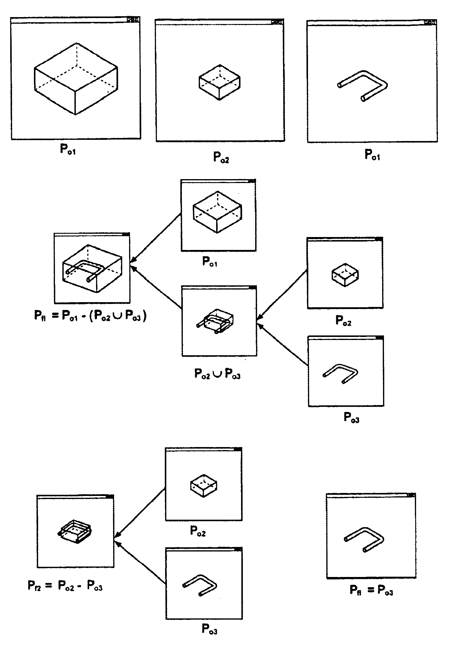
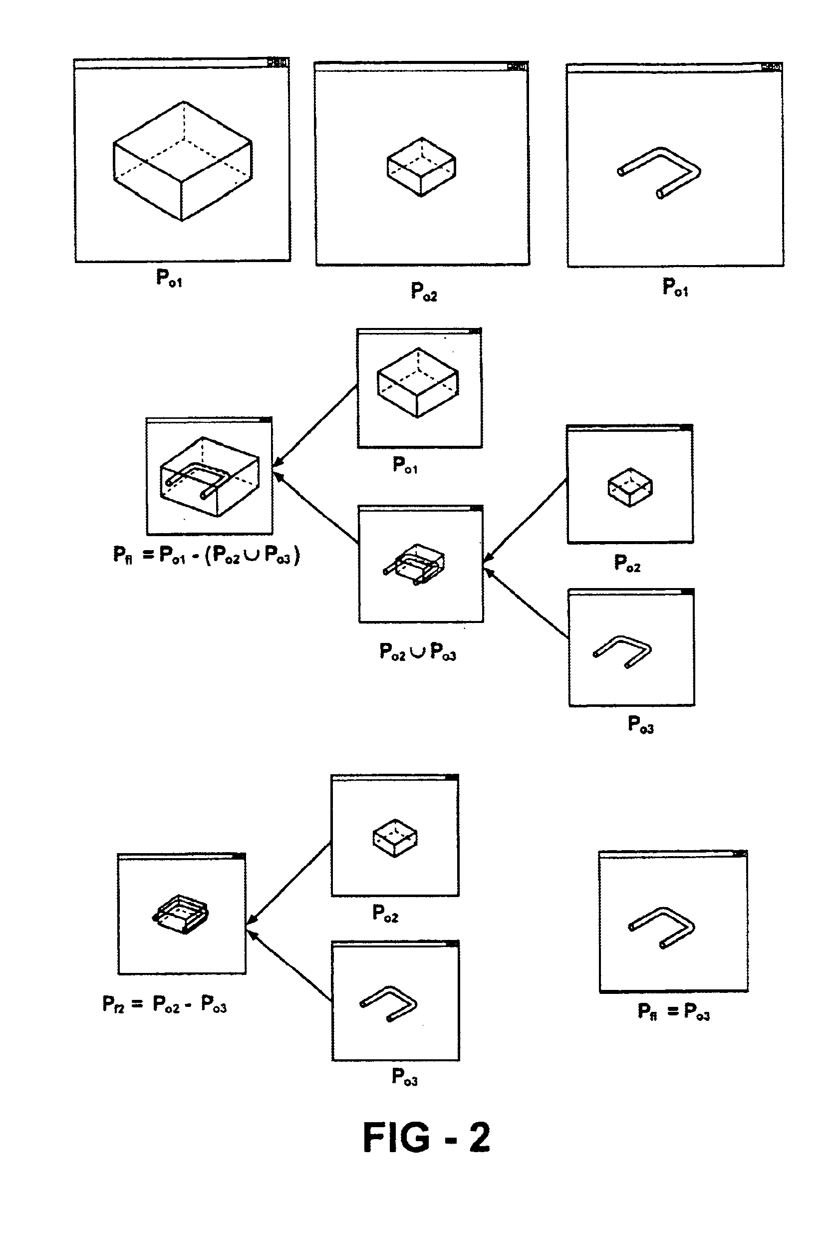
In direct metal deposition, or DMD™, the dimensions and overall geometry of a fabricated article are rendered in accordance with a computer-aided design (CAD) description. For all but the simplest of parts, the geometry must be described mathematically. Modeling of the shapes involved is achieved through the use of CAD systems, and from these representations, tool paths are generated to drive a numerically controlled additive process to manufacture the part.

In order to drive the DMD's CNC system, a text file called the part program (or toolpath file) is generated from commercial CAM software containing commands that are understandable to the CNC. The commands are loaded into the memory and executed. Typical commands are move commands, which tell the CNC to move to a new point at a given speed, turn on / off the laser and powder flow. These commands are all embedded directly within the part program when it is created, and are triggered at specific points in the program. Some parameters...


PUM


Abstract

A method of modeling multiple material parts for additive manufacturing processes such direct metal deposition operates within the constraints of a single material CAD system. Each material is modeled separately as a single or multiple solid part, under the assumption that there are no internal multiple materials; that is, no voids for other material parts. The parts are ordered from the outer most geometry to the innermost geometry and Boolean operations are performed to calculate the final volume for each part. In use of the invention, should any design changes occur, only the parts as originally defined need to be modified, and the method is reapplied. The method is applicable to the generation of CAM cutting paths for 2½-D and 3-D geometries by pocket machining with spiral-in, spiral-out, and arbitrary direction raster tool paths using stock material with and without reflection, depending upon the geometry. Single- and multi-material files may be merged one toolpath file, and commands may be embedded for closed- or open-loop control of the fabrication process.

Description

FIELD OF THE INVENTIONThis invention relates generally to the layered fabrication of three-dimensional components and, in particular, to a closed-loop system and method wherein tool paths are generated for multiple materials using a direct metal deposition process.BACKGROUND OF THE INVENTIONFabrication of three-dimensional metallic components via layer-by-layer laser cladding was first reported in 1978 by Breinan and Kear. In 1982, U.S. Pat. No. 4,323,756 issued to Brown et al., describes a method for the production of bulk rapidly solidified metallic articles of near-net shape, finding particular utility in the fabrication of certain gas turbine engine components including discs and knife-edge air seals. According to the disclosure, multiple thin layers of feedstock are deposited using an energy beam to fuse each layer onto a substrate. The energy source employed may be a laser or an electron beam. The feedstock employed in the practice of the invention may be either a wire or powd...

Claims


Application Information

Patent Timeline
Patent Type & Authority Patents(United States)
IPC IPC(8): G06F19/00G05B19/4099
CPCG05B19/4099G05B2219/49245G05B2219/35159G05B2219/35082Y02P90/02B33Y50/02
Inventor ALEXANDER, PAUL
Owner DM3D TECH
Why Eureka
Try Eureka