Watercraft and inflatable flooring therefor

a technology for inflatable watercraft and flooring, applied in the field of inflatable watercraft and to inflatable flooring therefor, can solve the problems of avoiding the diminished stability of some existing floors, and achieve the effect of avoiding diminished stability

Inactive Publication Date: 2005-03-01
ZODIAC INT
View PDF11 Cites 15 Cited by
  • Summary
  • Abstract
  • Description
  • Claims
  • Application Information

AI Technical Summary

Benefits of technology

The present invention provides alternate flooring including both inflatable and non-inflatable elements. Utilizing an inflatable core permits the flooring to support substantial loads while maintaining its lightweight nature. Such a high-pressure inflatable core additionally contributes to longitudinal and lateral rigidity of the flooring, avoiding diminished stability associated with some existing floors.

Problems solved by technology

Such a high-pressure inflatable core additionally contributes to longitudinal and lateral rigidity of the flooring, avoiding diminished stability associated with some existing floors.

Method used


Image

  • Watercraft and inflatable flooring therefor
  • Watercraft and inflatable flooring therefor
  • Watercraft and inflatable flooring therefor

Examples


Embodiment Construction

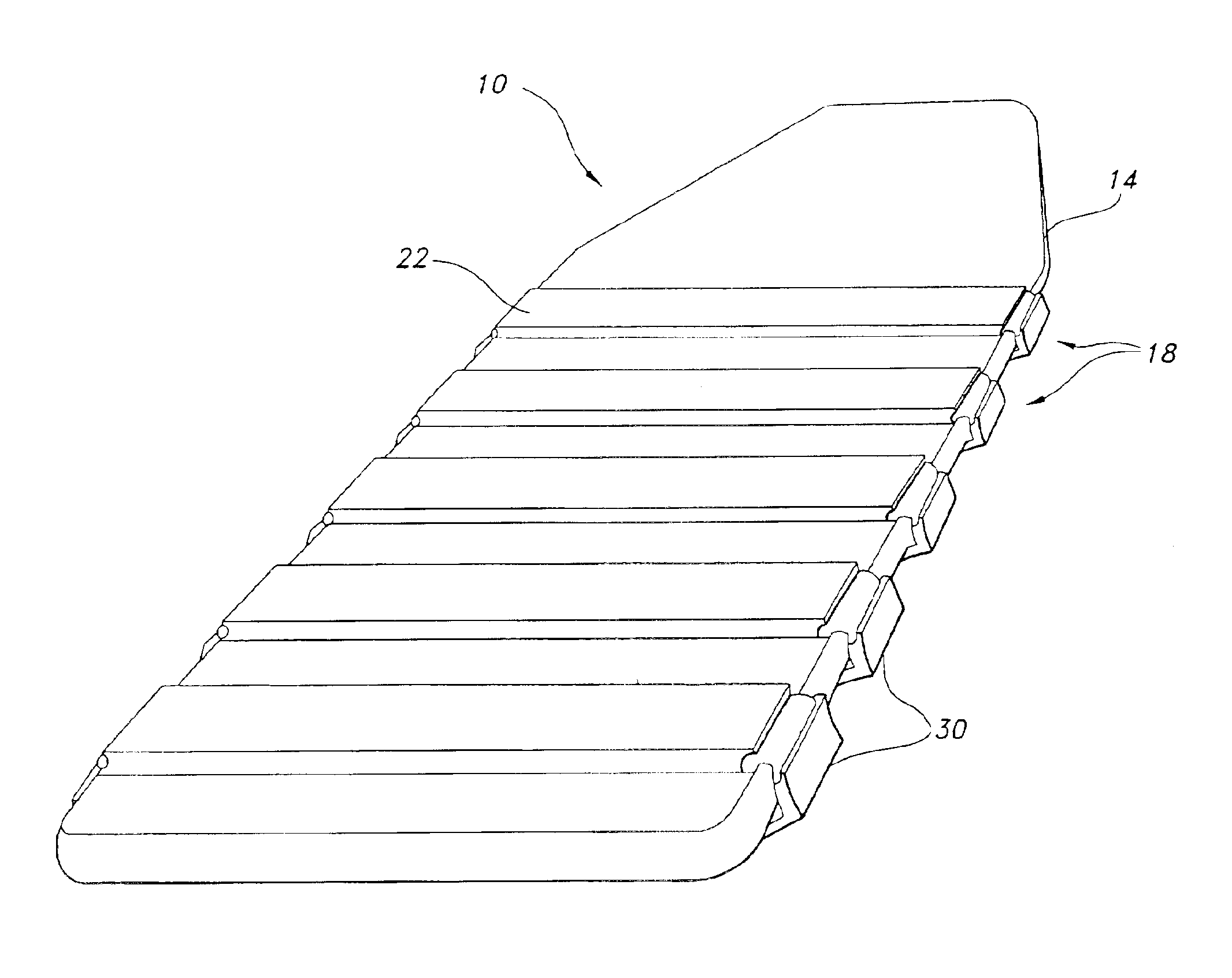
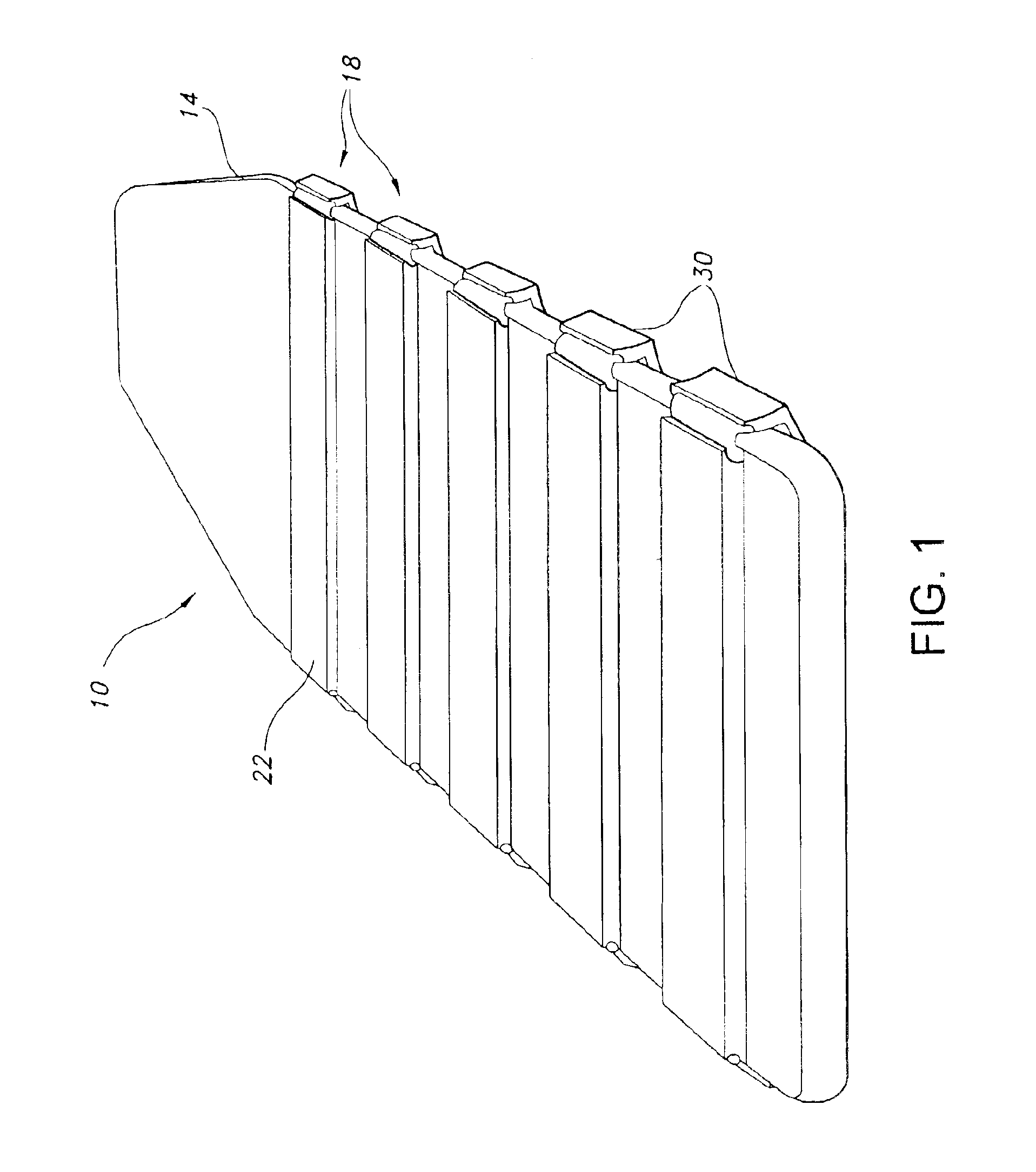
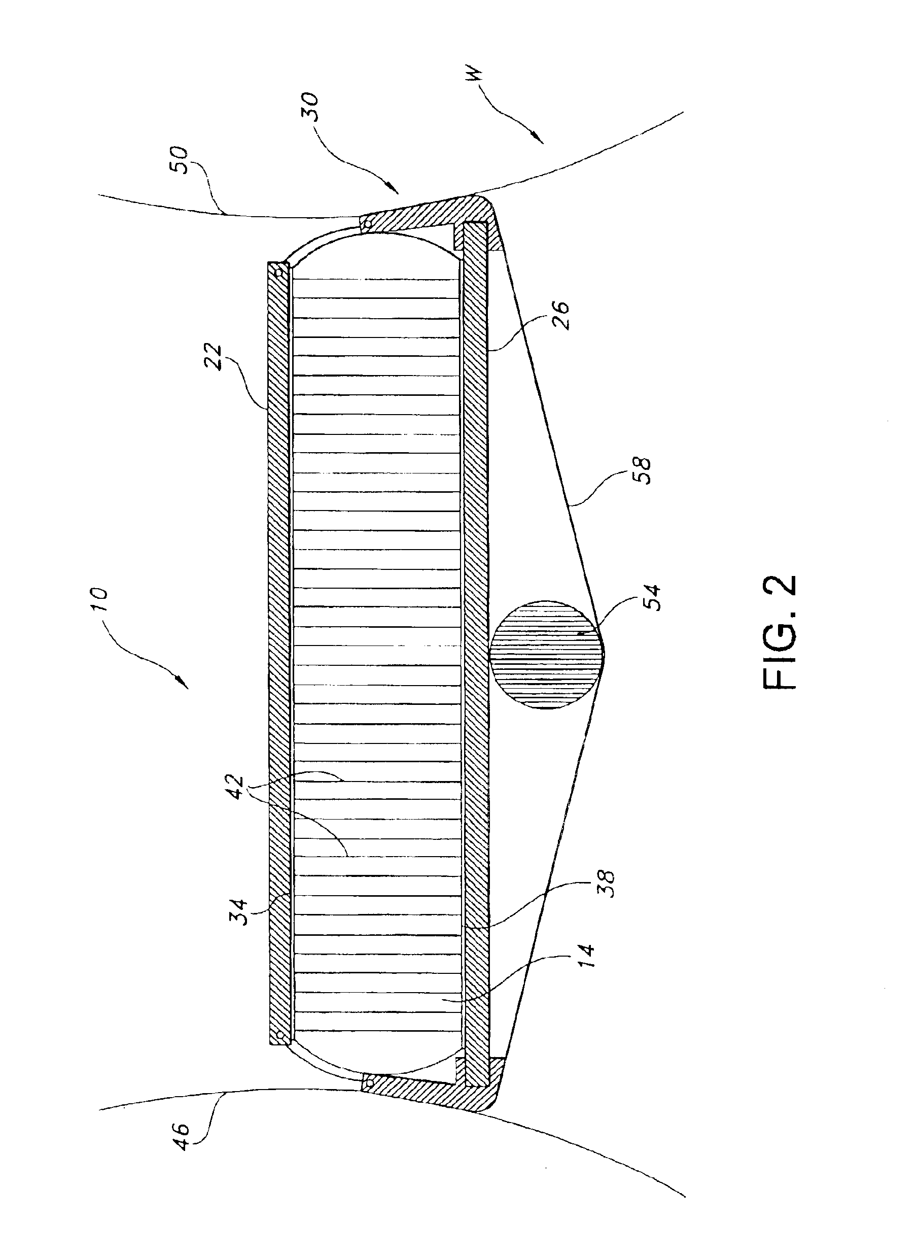
FIGS. 1-4 illustrate exemplary flooring 10 of the present invention. As detailed therein, flooring 10 may comprise core 14, lateral components 18 (comprising sets of upper and lower slats 22 and 26, respectively), and stringers 30. Although FIG. 1 illustrates five such components 18 and FIG. 4 illustrates six, those skilled in the art will recognize that more or fewer such components 18 may be utilized as part of any particular flooring 10. Likewise, although not presently preferred by the applicants, various of upper or lower slats 22 or 26 of the sets, or some or all of stringers 30, may be omitted if desired.

Core 14 preferably is inflatable with air or other gas. Using such a core 14 provides a lightweight way of providing flooring that may support substantial loads. Indeed, embodiments of core 14 may be designed to be inflated to relatively high pressures (on the order of one bar) for use in supporting quantities of troops and equipment being transported over water. Because so i...


PUM


Abstract

Watercraft flooring including both inflatable and non-inflatable elements is detailed. Such flooring may be designed to support substantial loads while maintaining its lightweight nature and contributing to its longitudinal and lateral rigidity. Some versions of the flooring have an inflatable core with slats positioned both above the upper surface of the core and below the lower surface of the core at regular intervals along its length. The slats extend laterally across substantially the width of the core, effectively sandwiching portions of the core between them.

Description

FIELD OF THE INVENTIONThis invention relates to watercraft, particularly (although not exclusively) to inflatable watercraft, and to inflatable flooring therefor.BACKGROUND OF THE INVENTIONU.S. Pat. No. 5,868,095 to Zeromski, et al., incorporated herein in its entirety by this reference, details exemplary inflatable flooring for watercraft such as inflatable boats. Flooring described in the Zeromski patent is denoted as “rigid” and comprises “at least one watertight enclosed chamber of a generally very flat shape and which can be inflated to a relatively high pressure.” The chamber is defined (in part) by upper and lower main walls, with each wall being formed ofat least one sheet of at least one flexible and airtight material. In general, each wall is constituted by an assembly of several sheets . . . which each have specific individual compositions and characteristics . . . . The two walls are also connected to each other by a multiplicity of flexible links such as threads, all of...

Claims


Application Information

Patent Timeline
Patent Type & Authority Patents(United States)
IPC IPC(8): B63B7/00B63B7/08
CPCB63B7/082B63B7/08
Inventor FLEMING, TIMOTHY
Owner ZODIAC INT
Why Eureka
Try Eureka