
Tubular boat having modular construction

a technology of modular construction and tubular boats, which is applied in the field of tubular boats, can solve the problems of high cost of producing a full line of boats which vary in size and configuration, high cost of traditional aluminum models, and labor-intensive processes, and achieve the effect of reducing costs

Inactive Publication Date: 2005-03-01
HENDERSON WILLIAM C
View PDF12 Cites 17 Cited by
  • Summary
  • Abstract
  • Description
  • Claims
  • Application Information

AI Technical Summary

Benefits of technology

The present invention has solved the problems cited above, and is an unsinkable, rigid hull, inflatable style boat which can be constructed in various configurations at reduced cost using modular components.
The great advantage provided by the present invention is the significantly reduced cost of production enabled by the ability to produce a variety of boats which vary in length and functional characteristics without requiring an additional dedicated mold or tooling for each variation. An entire line of boat models can be produced from the same bow module, sidewall module, and transom module designs, each produced from a single dedicated mold. And, because the molds required for these individual components are significantly smaller than the massive molds required for conventional boat designs, the mold fabrication cost and the size of the facility for mold storage and boat production can be drastically reduced, even for a single model.

Problems solved by technology

Because each mold is costly, and because the size of the molds requires a large facility for storage and production, the cost of producing a full line of boats which vary in size and configuration can quickly become exorbitant.
Traditional aluminum models face similar cost disadvantages.
This is a costly, labor-intensive process that is usually only cost effective for custom boats.
On the other hand, large-scale production requires large dedicated dies and jigs for forming and assembling the aluminum hull panels, resulting in cost and space requirements paralleling those associated with production of fiberglass boats using dedicated molds.
However, in more extreme conditions, such as shallow reefs and rocky coastlines, or during inclement weather conditions, these traditional configurations often lack the stability and sea-worthiness necessary for safe operation, and in particular retain minimal buoyancy when swamped.
Although this adds a degree of safety, a bladder failure can still strand the occupants or significantly reduce travel speed, creating a situation that is inconvenient at best and life threatening at worst.
While RHIB-style boats with foam filled collars are among the most robust and seaworthy craft available, prior versions have generally required dedicated molds for construction of the rigid collar thus incurring expenses and difficulties similar to those discussed with regard to the production of traditional, open hulled boats.
As a result, the introduction of each new model having significant dimensional changes has required a new, expensive, dedicated mold, imposing a significant cost burden on the manufacturer and ultimately the consumer.
This provides a high degree of stability and a smooth ride on calm waters, however, in rough conditions this configuration tends to pound the waves, which is detrimental to both stability and passenger comfort.
An alternative is to provide the craft with more of a V-shaped hull / floor unit and position it deeper with respect to the collar, which provides a smoother ride and better seaworthiness in rough conditions by cutting through the waves, but at the expense of rendering the craft more “tippy” and less maneuverable under calm water conditions.
Unfortunately, the types of constructions used in prior RHIB-style boats are unable to accommodate both configurations without doubling the number of models offered and assuming the financial penalties associated with the additional molds and tooling.

Method used


Image

  • Tubular boat having modular construction
  • Tubular boat having modular construction
  • Tubular boat having modular construction

Examples


Embodiment Construction

a. Overview

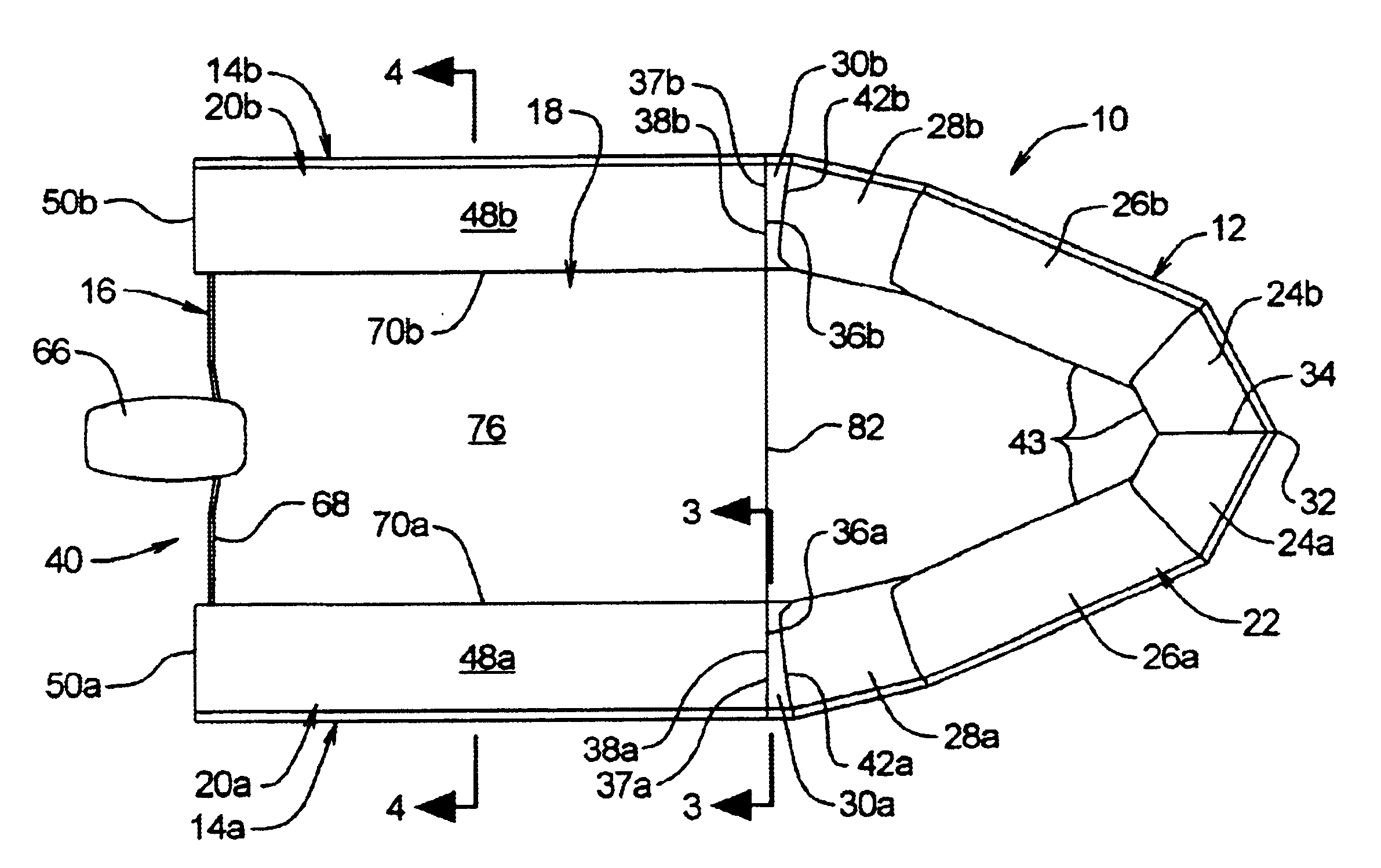
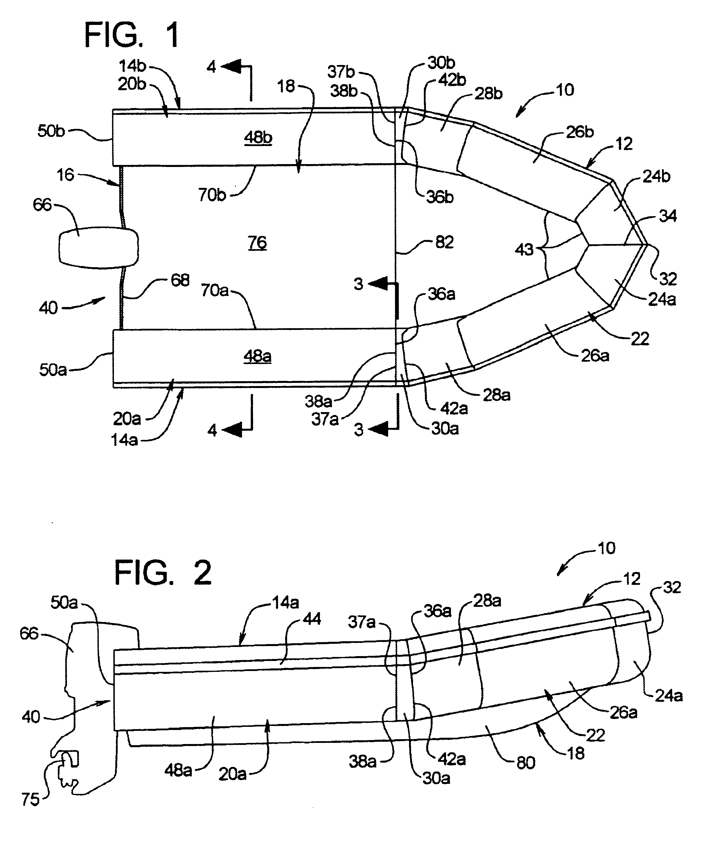
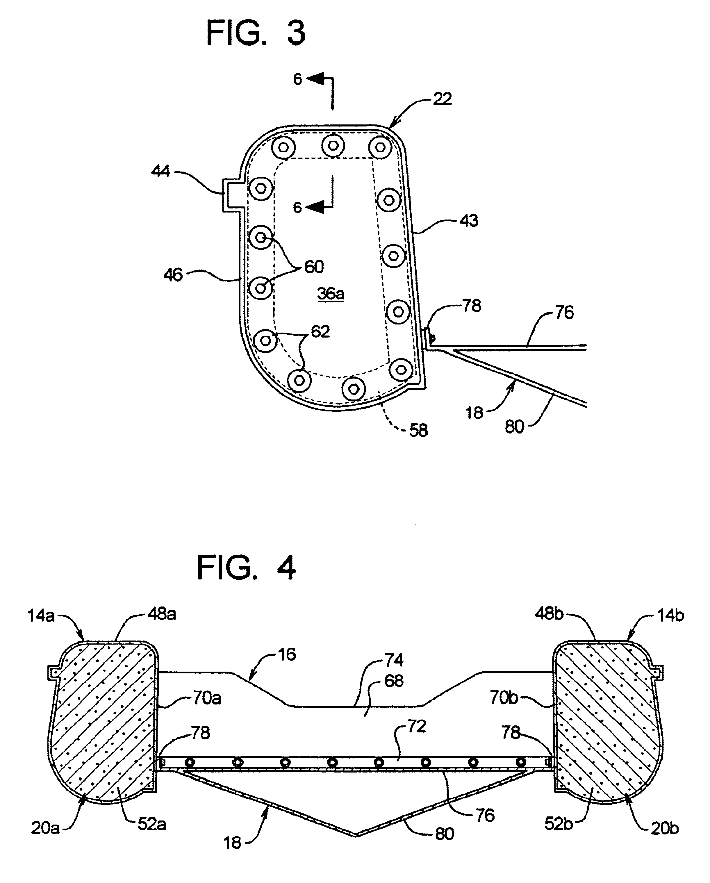
FIG. 1 shows a top view, and FIG. 2 shows a side view of RHIB-style boat 10 in accordance with the present invention. As can be seen, the boat 10 includes four, interconnected modular assemblies, namely a bow assembly 12, right and left gunwale assemblies 14a,b, a transom unit 16, and a rigid floor / hull unit 18.

The identical bow assembly 12 and transom unit 16 may be used in all boats produced, regardless of length or hull configuration. In the embodiment illustrated in FIGS. 1 and 2, the gunwale assemblies 14a,b each comprise a single gunwale module 20a,b and thus define the limiting minimal length for the modular boat 10. For production of longer boats a lengthened version of the hull assembly 18 may be substituted, with additional gunwales modules connectively butted to the leading modules 20a,b to make up the difference in length. As will be described in greater detail below, the floor / hull unit 18 is then mounted to the bow and gunwale modules at a relatively higher ...


PUM

PropertyMeasurementUnit
lengthaaaaaaaaaa
lengthaaaaaaaaaa
heightaaaaaaaaaa

Abstract

A rigid hull inflatable style boat constructed of rigid-shell modules. Modular gunwale sections are mounted to the trailing ends of a modular bow section to form the a flotation collar. Boats having greater / shorter lengths can be constructed by increasing or decreasing the number of gunwale modules. The bow and gunwale modules may be formed of molded polyethylene filled with hydrophobic foam material. The floor / hull module can be mounted at varying heights within the flotation collar to alter the performance characteristics of the craft. The hull module may have a V-shaped hydrodynamic contour, so that when the hull module is mounted relatively high within the collar the boat has a sponson-type hull form, and when the hull module is mounted relatively low within the flotation collar the boat has a V-type hull configuration. The flotation modules have a generally D-shaped configuration, with flat, vertically extending inboard walls that mate with a vertically-extending flange on the floor / hull module so that the latter can be adjusted to a higher or lower position within the collar during assembly.

Description

BACKGROUND OF THE INVENTIONa. Field of the InventionThe present invention relates generally to boats having tubular flotation members and, more particularly, to a form of construction that allows tubular boats having a variety of lengths and configurations to be produced at reduced cost using modular components.b. Background ArtTypically, small recreational boats are fabricated from fiberglass or aluminum in a rigid, open-hull configuration. The fiberglass versions generally require a dedicated mold designed specifically for each particular size and style of vessel. Because each mold is costly, and because the size of the molds requires a large facility for storage and production, the cost of producing a full line of boats which vary in size and configuration can quickly become exorbitant.Traditional aluminum models face similar cost disadvantages. In some cases, the aluminum versions are hand fabricated using sheet metal forming and welding techniques. This is a costly, labor-inten...

Claims


Application Information

Patent Timeline
Patent Type & Authority Patents(United States)
IPC IPC(8): B63B5/00B63B5/24B63B3/00B63B3/08
CPCB63B3/08B63B7/04B63B5/24
Inventor HENDERSON, WILLIAM C
Owner HENDERSON WILLIAM C
Learn More