Workpiece transfer device for machine tools

a technology of machine tools and transfer devices, which is applied in the direction of pile separation, transportation and packaging, manufacturing tools, etc., can solve the problems of increasing the cost of the whole device, increasing the cost of the transfer device, and vibration and/or noise, so as to reduce the number of components, prevent vibration or noise, and position adjustment

Inactive Publication Date: 2005-03-01
DMG MORI CO LTD
View PDF9 Cites 16 Cited by
  • Summary
  • Abstract
  • Description
  • Claims
  • Application Information

AI Technical Summary

Benefits of technology

The present invention has been accomplished in view of these circumstances. An object of the present invention is to provide a workpiece transfer device for machine tools that is capable of easily achieving positional adjustment of the rack while suppressing increases in cost and preventing occurrences of vibrations and noise.
With the workpiece transfer device according to the first aspect, since the linear guide is disposed on one wall surface of the frame member and the rack is disposed on another adjoining wall surface, positional adjustment of the rack relative to the linear guide can be fulfilled with ease. Moreover occurrence of vibrations or noise can be prevented while reducing the number of component parts. Also, since only one fitting surface for the linear guide can be used, the frame member may have a lower dimensional accuracy when compared with the cases where two linear-guide fitting surfaces are necessary.
Further, since the rack thickness can be increased without increasing the height of the support member, warping of the rack during the tooth-cutting process can be prevented.
With the workpiece transfer device according to another aspect of the invention, since the linear guide and the rack are disposed on one same wall surface of the frame member, positional adjustment of the rack relative to the linear guide can be fulfilled with ease. Moreover occurrence of vibrations or noise can be prevented while reducing the number of component parts so that the same benefits can be obtained.
Also, since the linear guide and the rack are disposed on the same wall surface, it is only necessary to perform planar machining on one side wall surface, thus allowing the machining costs to be reduced compared with the cases where two wall surfaces must be subjected to machining.

Problems solved by technology

This causes a problem in that the cost for the whole device increases.
This accuracy also increases the cost of the transfer device.
If the vertical position is not properly adjusted then vibrations and / or noise can occur.
Performing a machining process on the wall surfaces of the frame member 60 could solve the above problem; however, doing so would lead to impractical increases in cost.

Method used


Image

  • Workpiece transfer device for machine tools
  • Workpiece transfer device for machine tools
  • Workpiece transfer device for machine tools

Examples


second embodiment

FIG. 6 is a view for explaining a workpiece transfer device according to the present invention. In this figure, the same reference numerals are used as those in FIG. 5 to show the same or equivalent component members.

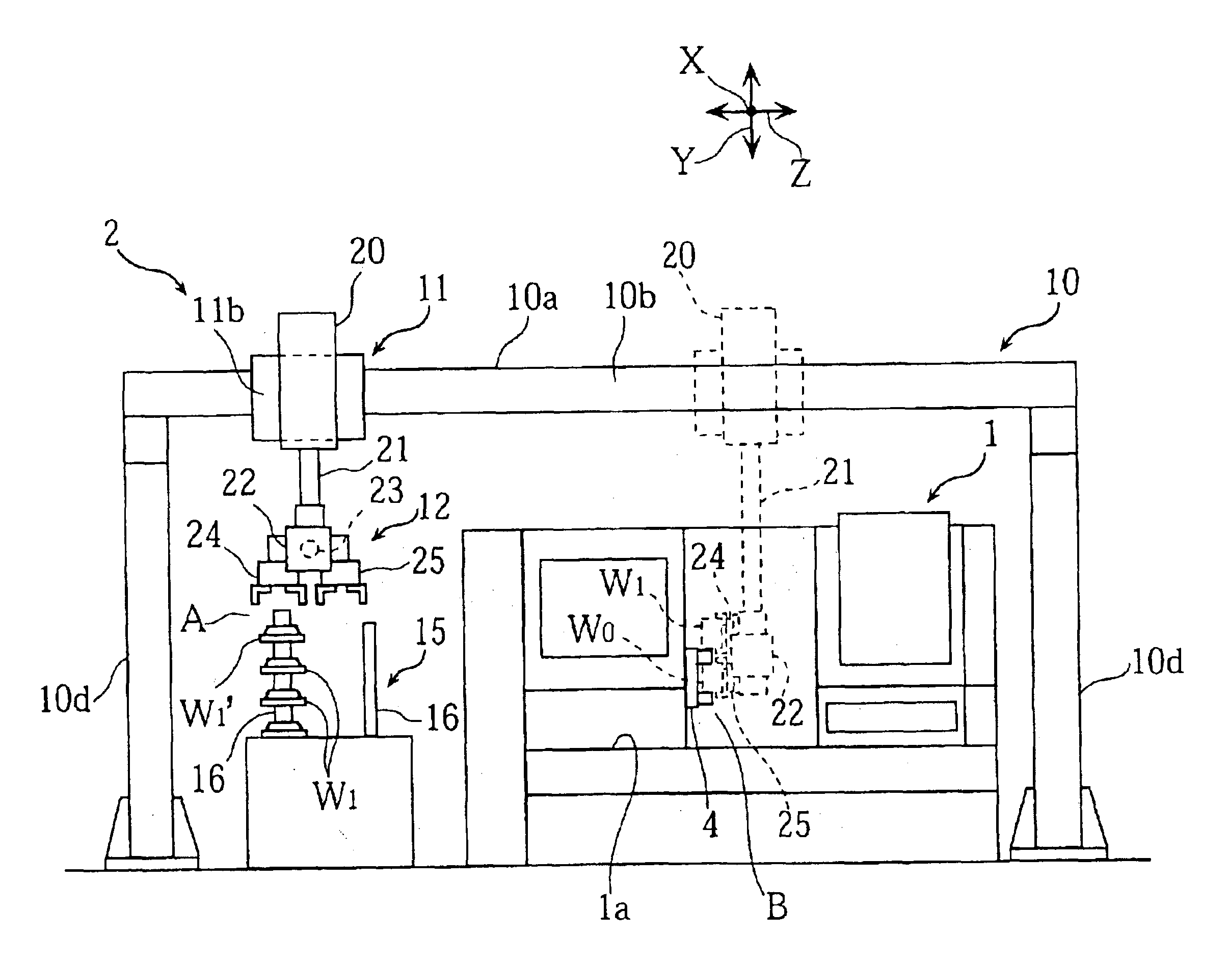
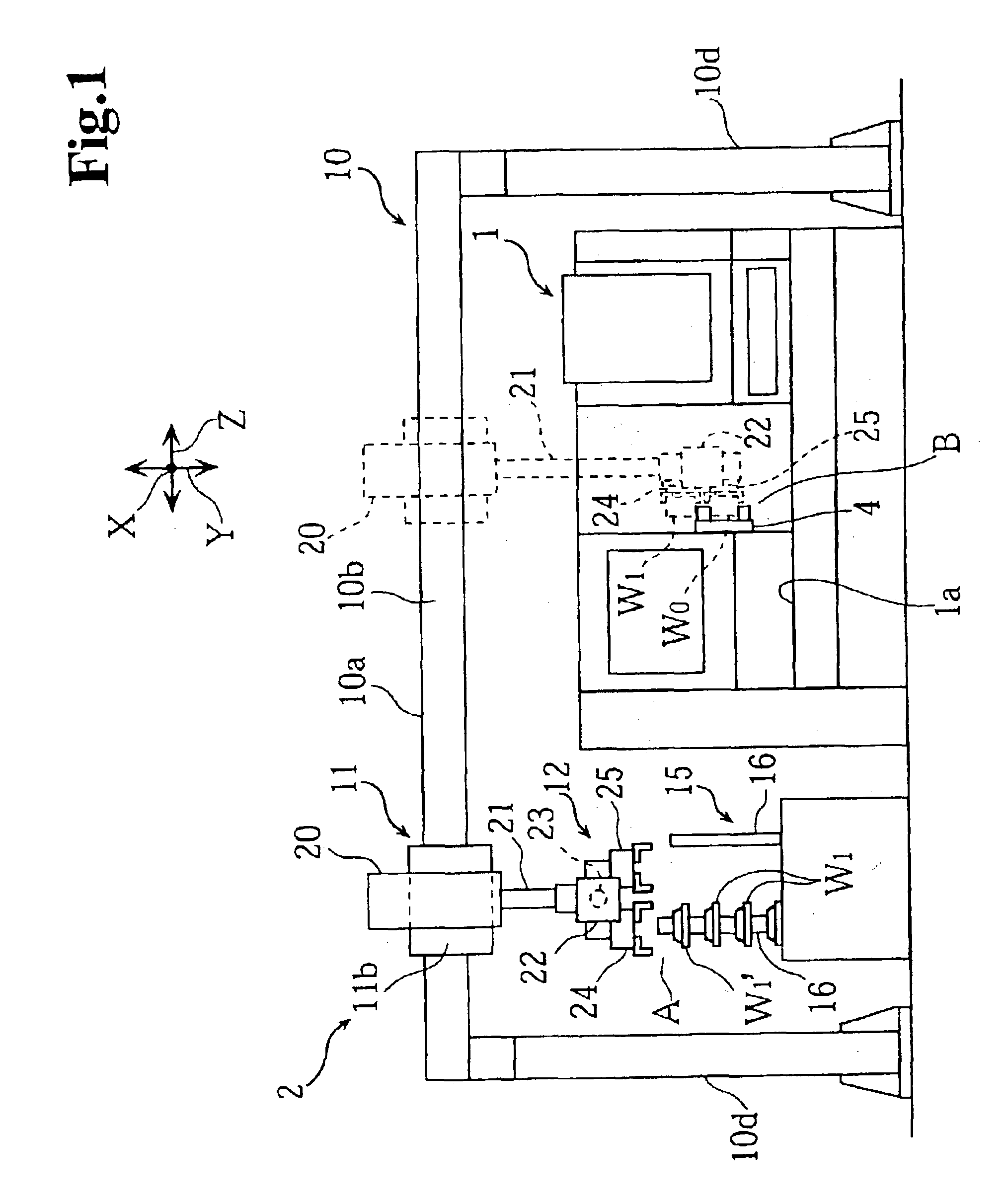
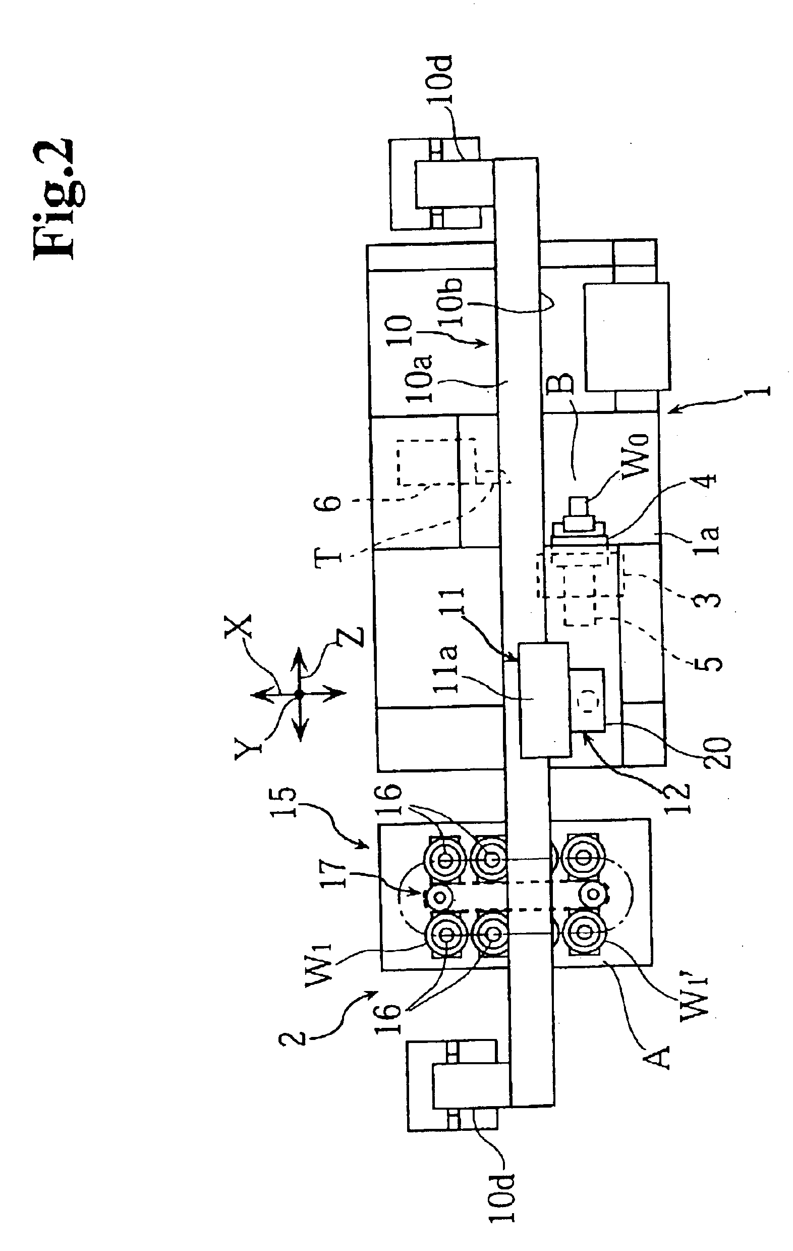
The workpiece transfer device 2 of this embodiment comprises a frame member 10 extending from a workpiece loading / unloading position A to a workpiece machining position B, a support member 11 supported by the frame member 10 so as to be movable in the Z-axis direction, a workpiece holding mechanism 12 mounted on the support member 11, and a drive mechanism 7. The basic construction of this workpiece transfer device 2 is similar to that of the first embodiment.

Further, a linear guide 27 and a rack 30 are disposed on a front side wall 10b of the frame member 10. This linear guide 27 is fixedly placed at an upper end portion of the front side wall 10b, and the rack 30 is disposed at a lower end portion of the front side wall 10b so its vertical position relative to the lin...


PUM

PropertyMeasurementUnit
shapeaaaaaaaaaa
structureaaaaaaaaaa
thicknessaaaaaaaaaa

Abstract

A workpiece transfer device for machine tools that easily achieves positional adjustment of the rack while suppressing increases in cost and therefore preventing occurrences of vibrations and noise is disclosed. The workpiece transfer device includes a frame member having a rectangular cross-section. The device extends from a workpiece machining position to a workpiece loading / unloading position. A support member is hung on the frame member so as to be movable via a linear guide and which has a workpiece holding mechanism mounted thereon. A drive mechanism for rotationally driving a pinion gear engaged with a rack is provided on the frame member so as to be parallel to the linear guide so that the support member is moved between the two positions. The linear guide is disposed on one wall of the frame member and the rack is disposed on another wall surface so as to have its position adjustable.

Description

BACKGROUND OF THE INVENTION1. Field of the InventionThe present invention relates to a workpiece transfer device for machine tools. The device is constructed so that a support member having a workpiece holding mechanism is mounted on a frame member and is extendable between a workpiece machining position and a workpiece loading / unloading position via a linear guide. The support member is moved in a reciprocating motion by a rack-and-pinion drive mechanism.2. Discussion of the Related ArtIn recent years, some machine tools are equipped with a workpiece transfer device that is designed to automatically and continuously perform such working processes as receiving an unprocessed workpiece from the workpiece stocker disposed at the workpiece loading / unloading position, loading the workpiece in a chuck of a spindle (which is at the workpiece machining position), receiving the processed workpiece from the chuck of the spindle, and unloading the workpiece at the workpiece stocker.FIG. 8 sho...

Claims


Application Information

Patent Timeline
Patent Type & Authority Patents(United States)
IPC IPC(8): B23Q5/22B23Q5/38B23Q7/04B23Q1/00B23Q1/01
CPCB23Q1/012B23Q7/04B23Q5/385
Inventor WATANABE, MICHIOOKUYAMA, YOSHINOBU
Owner DMG MORI CO LTD
Why Eureka
Try Eureka