
Horizontal pipe handling device

Inactive Publication Date: 2005-03-01
AKER KVAERNER MH
View PDF10 Cites 47 Cited by
  • Summary
  • Abstract
  • Description
  • Claims
  • Application Information

AI Technical Summary

Benefits of technology

One object of the invention has been to provide pipe handling equipment that may operate independently and in parallel with any drilling activities that may be in progress in the derrick. This means that the piping goods must be able to be moved between a horizontal position and a vertical position in or by the derrick, and vice versa, while a drilling machine and drill string is in operation in the drilling centre in the derrick. In the case of a retrieval operation involving the entire drill string, this will have particular significance, as it will speed the operation up considerably compared with what has been possible up until today.
It is also an object of the present invention to enable the centre of gravity to be lowered and the wind catchment area to be reduced for a floating installation, while retaining efficient pipe handling.
Moreover, the present invention aims to improve the utilisation of the available space and / or reduce the size of the drill floor, by reducing or eliminating the need for storage of pipes on the drill floor. According to the present invention, this is achieved by making the handling of pipes in the pipe rack, and to and from this, more efficient, and more particularly by a transport carriage including picking devices that are designed to pick up pipes lying substantially in the horizontal position at different levels in a pipe rack.

Problems solved by technology

This task is heavy and entails a great danger to life, health and materials.
As the equipment used is very expensive, the time it takes from when the equipment is put into service, i.e. the drilling is initiated, until the production starts, will to a large extent be decisive in the cost of the development.
Furthermore, the fact that standing pipes or stands contribute towards giving the drilling or production installation a high centre of gravity, is increasingly becoming a problem.
A high centre of gravity in such installations causes instability.
As such, it becomes difficult to satisfy the requirements for stability.
This means that other equipment must be moved down, possibly also involving an increase in ballast.
This leads to less flexibility in the utilisation of the available space.
In the case of vertically stored pipes, the wind catchment area also increases, which in combination with a high centre of gravity may have fatal consequences.
This has however involved awkward and time consuming pipe handling.

Method used


Image

  • Horizontal pipe handling device
  • Horizontal pipe handling device
  • Horizontal pipe handling device

Examples


Embodiment Construction

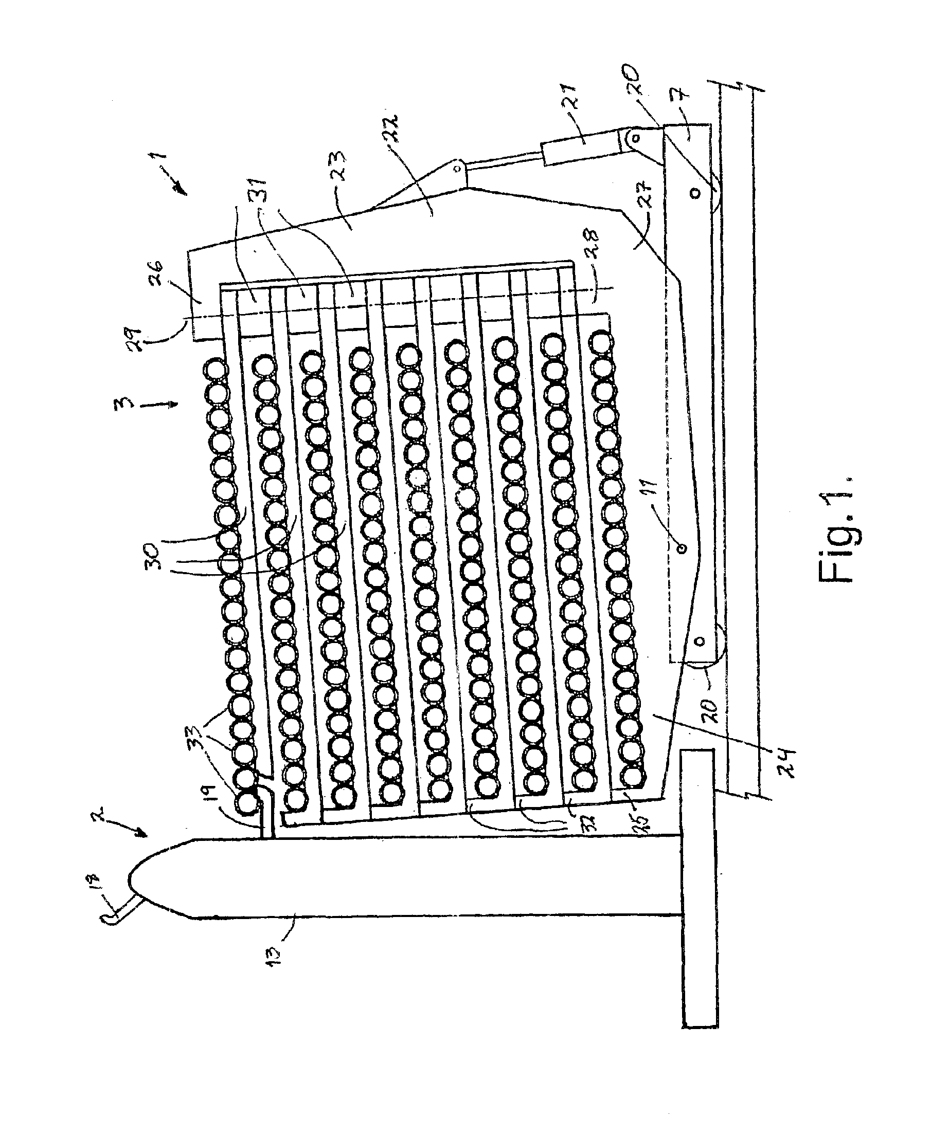
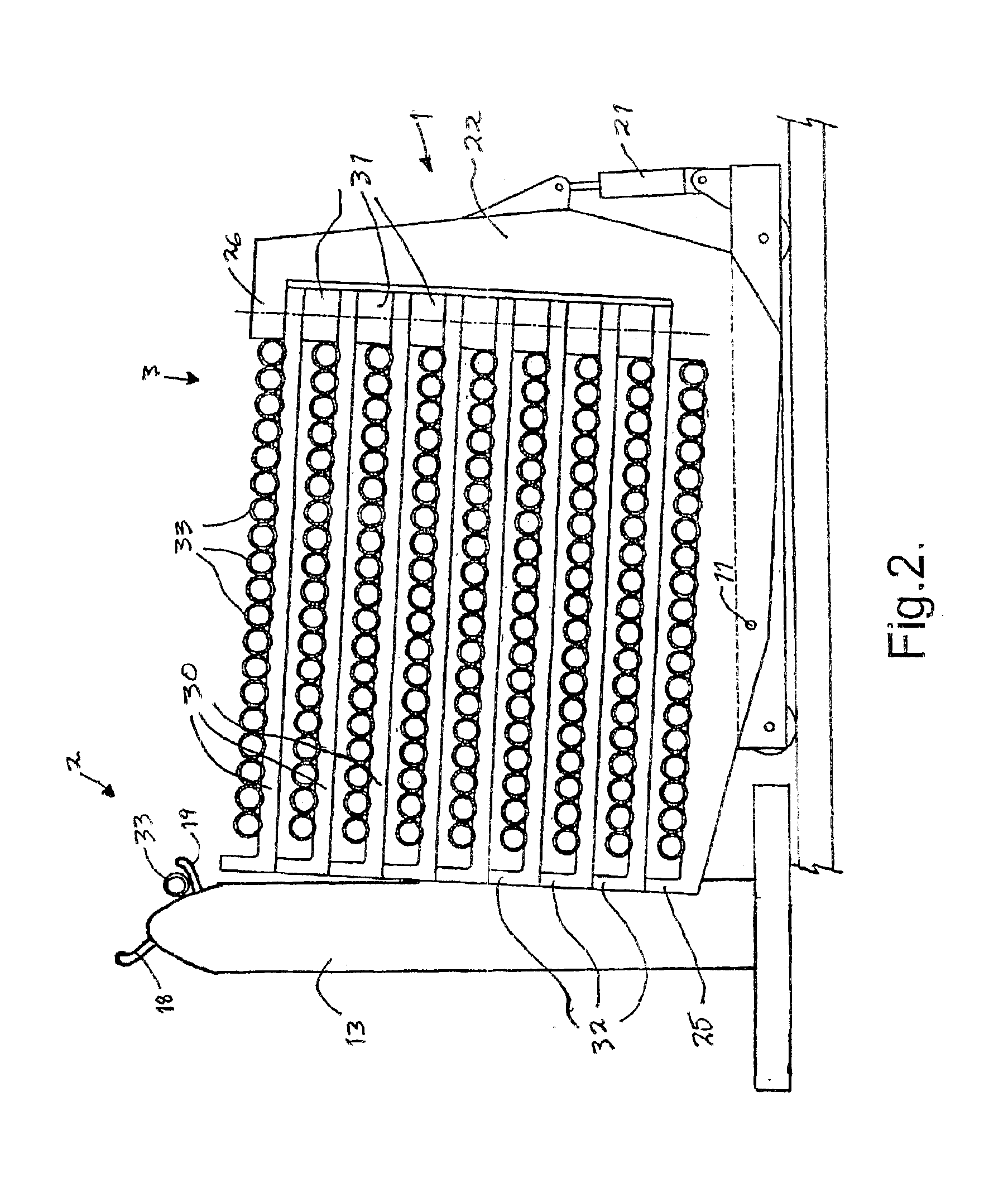
The pipe storage device 1 comprises two supporting blocks 3 and 4 that are interconnected via a base frame 5 including two transverse beams 6 and 7 and two longitudinal beams 8 and 9. Each supporting block 3 and 4 is arranged in a tilting manner about a mounting 10 and 11 respectively in the transverse beam 6 and 7 respectively. Means are provided (not shown) for synchronization of the tilting motion of the supporting blocks 3 and 4.

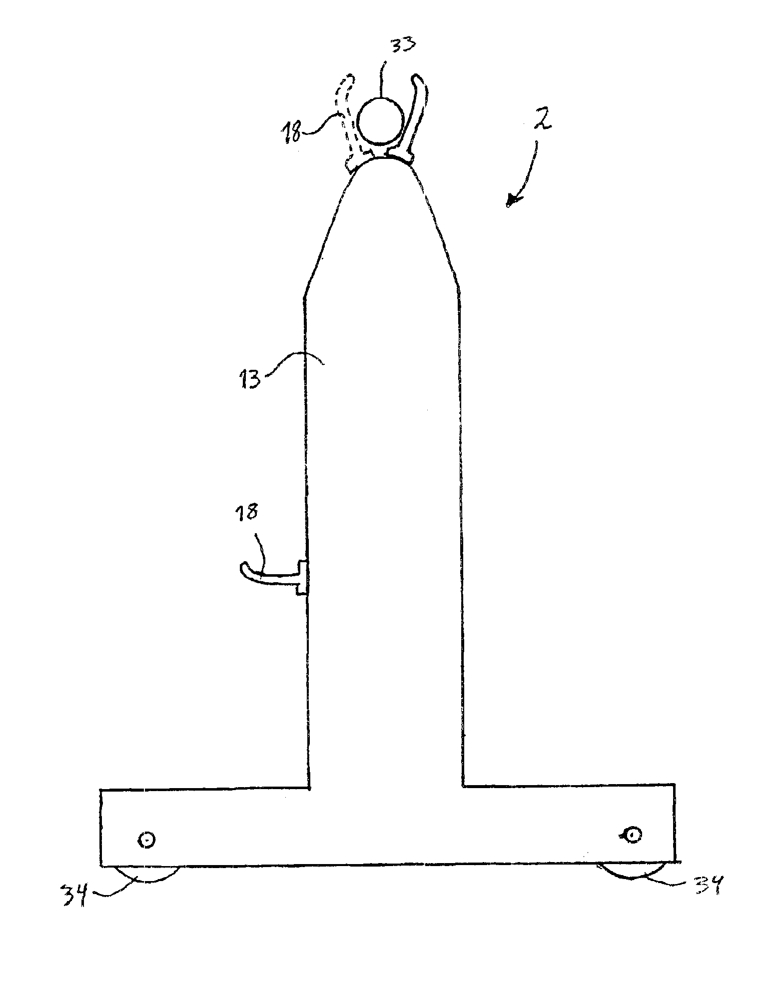
The pipe picking device 2 acts as a transport carriage for pipes to be transported between the storage device 1 and e.g. a lifting beam for raising pipes from a horizontal to a vertical position in order to bring this into the derrick, and includes picking columns 12 and 13, which are located on a base frame 14 that includes a longitudinal beam 15 and a transverse beam 16 and 17 at either end of the longitudinal beam 15. Each picking column is equipped with two picking arms 18 and 19. The picking columns 12 and 13 may advantageously be moved along the lo...


PUM


Abstract

A device for handling pipes or stands including a transportation carriage for transport of pipes or stands between a pipe storage and a place for use. The carriage includes picking columns, each having a first picking arm arranged to move substantially vertically. The arms are capable of lifting at least one horizontal pipe or stand from the pipe storage. The picking columns are also equipped with a respective second picking arm, capable of motion substantially vertically on the opposite side of the picking column, to hold the pipe or stand between the first and second picking arms. Also described are a storage device and a pipe erecting device to be used together with the transportation carriage.

Description

BACKGROUND OF THE INVENTION1. Field of the InventionThe present invention regards devices for handling pipes, especially devices for handling pipes in connection with petroleum production.2. Description of the Related ArtIn petroleum production, a large number of pipes is used for various purposes. When drilling a well, a total of up to several kilometres of drill pipes may be used, each of which pipes is generally approximately 10 m long. Prior to use, these pipes are stored in horizontal stacks on deck. The pipes are connected by threes to form so-called stands. During drilling, the pipes are stored vertically as stands in so-called finger boards on the drill floor, up along the derrick. During drilling, the entire drill string must be withdrawn from the well at certain intervals, so-called tripping, e.g. in order to change the drill bit. With today's technology, the pipes are inserted back into the finger boards in order to be easily accessible for future use.Up to several kilome...

Claims


Application Information

Patent Timeline
IPC IPC(8): E21B19/00E21B19/15
CPCE21B19/155E21B19/15
Inventor SLETTEDAL, PER
Owner AKER KVAERNER MH
Learn More