
Method of determining the efficiency of a dialyzer of a dialysis machine and a dialysis machine for carrying out this method

a dialysis machine and dialyzer technology, applied in the field of dialyzers, can solve the problems of reducing the efficiency of dialyzers and dialysis treatment, and the relative long measurement time has proved to be a disadvantage for monitoring the course of dialysance over time during dialysis treatment, and achieve the effect of precise information about dialyzers or dialysis

Inactive Publication Date: 2005-03-01
FRESENIUS MEDICAL CARE DEUTSCHLAND GMBH
View PDF6 Cites 111 Cited by
  • Summary
  • Abstract
  • Description
  • Claims
  • Application Information

AI Technical Summary

Benefits of technology

The object of the present invention is to provide a method which makes it possible to easily monitor the efficiency of a dialyzer during a dialysis treatment without any delay and to create a dialysis machine which permits simple monitoring of the efficiency of the dialyzer without any delay.
Essentially, the clearance and / or dialysance can be estimated throughout the course of the entire dialysis treatment on the basis of the clearance and / or dialysance established at a given dialysis fluid rate, blood flow rate or ultrafiltration rate. To enhance accuracy, the entire dialysis treatment can also be divided into individual time segments in which the monitoring is then performed on the basis of one measurement per individual time segment.
In this way it is possible to obtain very precise a information about the efficiency of a dialyzer or a dialysis treatment without having to interrupt the treatment by too frequent measurements of the clearance and / or dialysance. Such measurements could otherwise result in impairment of the actual dialysis treatment, depending on the measurement method and the frequency of the measurements.

Problems solved by technology

In this method, the relatively long measurement time has proven to be a disadvantage for monitoring the course of dialysance over time during the dialysis treatment.
One disadvantage of this method is that it allows a determination of only the maximum dialysance, but not of the dialysance for any desired dialysis fluid or blood flow rate.

Method used


Image

  • Method of determining the efficiency of a dialyzer of a dialysis machine and a dialysis machine for carrying out this method
  • Method of determining the efficiency of a dialyzer of a dialysis machine and a dialysis machine for carrying out this method
  • Method of determining the efficiency of a dialyzer of a dialysis machine and a dialysis machine for carrying out this method

Examples


Embodiment Construction

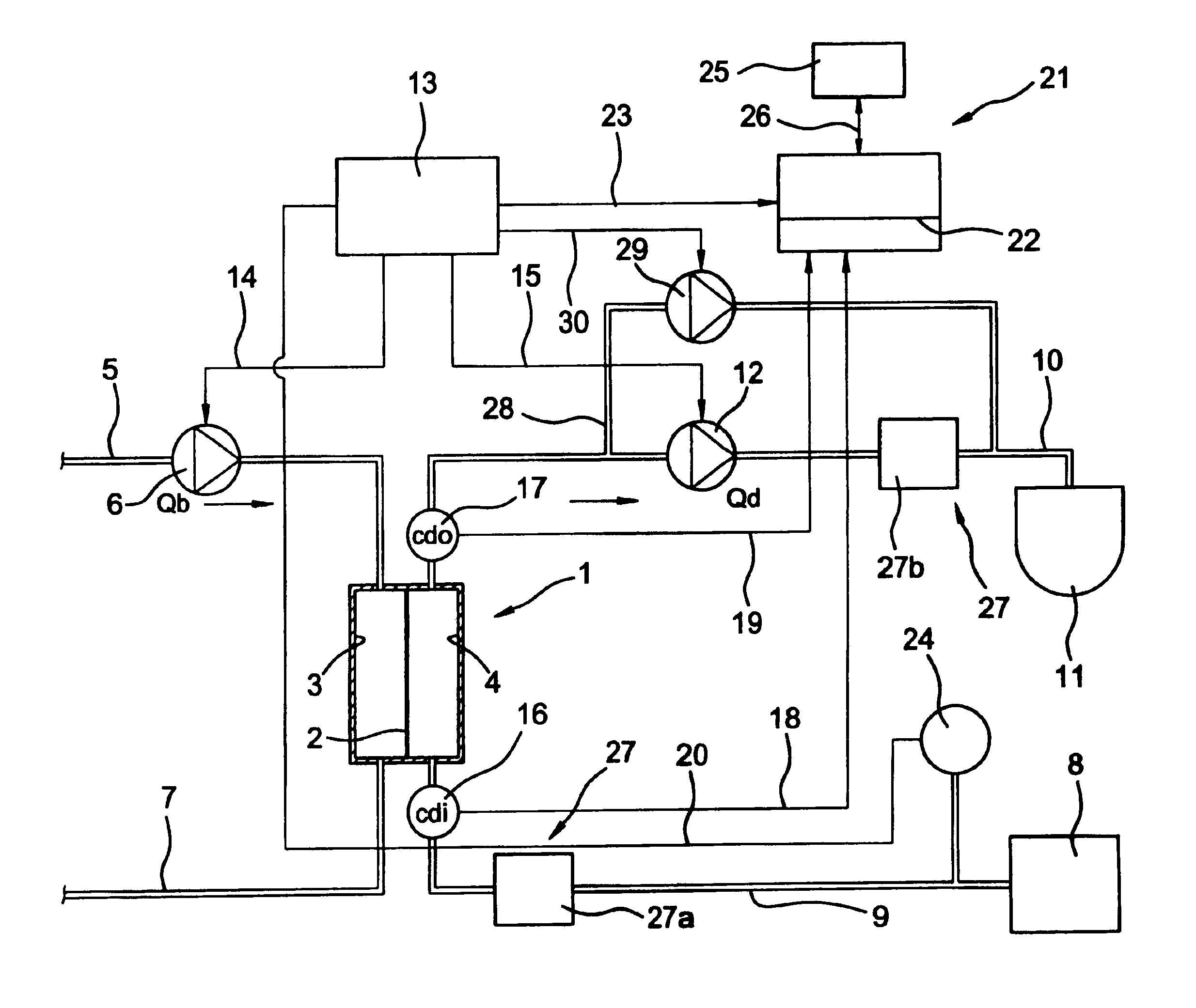
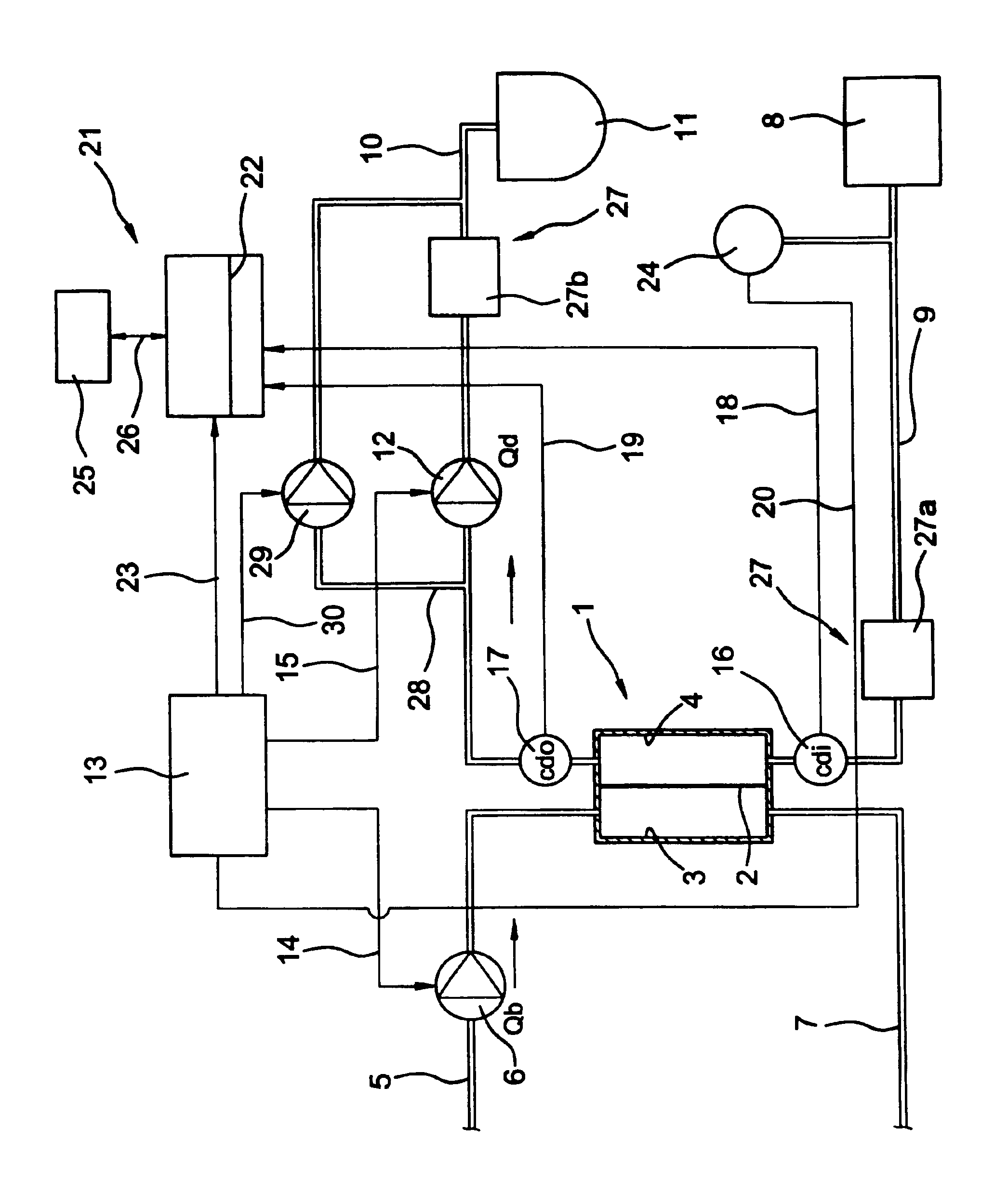
The dialysis machine has a dialyzer 1 divided by a semipermeable membrane 2 into a blood chamber 3 and a dialysis fluid chamber 4. An arterial blood line 5 connected to the inlet of the blood chamber 3 is also connected to a blood pump 6. Downstream from the blood chamber, a venous blood line 7 leads from the outlet of the blood chamber to the patient.

Fresh dialysis fluid is kept on supply in a dialysis fluid source S. A dialysis fluid inlet line 9 leads from dialysis fluid source 8 to the inlet of dialysis fluid chamber 4 of dialyzer 1, while a dialysis fluid outlet line 10 leads from the outlet of the dialysis fluid chamber to a drain 11. A dialysis fluid pump 12 is connected to dialysis fluid outlet line 10.

A balancing device 27 provided for balancing the fluid flowing into and out of the dialyzer has a balancing chamber with two balancing chamber halves 27a, 27b, the first of which is connected to the dialysis fluid inlet line 9 and the second to the dialysis fluid outlet line 1...


PUM

PropertyMeasurementUnit
blood flow rate Qbaaaaaaaaaa
flow rateaaaaaaaaaa
fluid flow rateaaaaaaaaaa

Abstract

A method and a device for determining the efficiency of a dialyzer of a dialysis machine during a dialysis treatment wherein the dialyzer is divided by a semipermeable membrane into a blood chamber and a dialysis fluid chamber and wherein the blood flows at a predetermined flow rate through the blood chamber and dialysis fluid flows at a predetermined flow rate through the dialysis fluid chamber. In use, the dialysance or clearance for a predetermined dialysis fluid flow rate and / or blood flow rate is measured, and then the dialysance or clearance for any dialysis fluid flow rate and blood flow rate is calculated.

Description

FIELD OF THE INVENTIONThe present invention relates to a method of determining the efficiency of a dialyzer of a dialysis machine during a dialysis treatment wherein the dialyzer is divided by a semipermeable membrane into a blood chamber and a dialysis fluid chamber and wherein blood flows at a predetermined flow ii rate through the blood chamber and dialysis fluid flows at a predetermined flow rate through the dialysis fluid chamber. In addition, the present invention relates to a dialysis machine for carrying out this method.BACKGROUND OF THE INVENTIONMass exchange in the dialyzer has both a convective component and a diffusive component. In diffusive mass exchange, the mass transfer per unit of time for the respective substance through the membrane is proportional to the concentration gradient between the blood and the dialysis fluid. In convective mass transport, the mass transfer depends on the quantity of filtrate, because the concentration of filterable substances is the sam...

Claims


Application Information

Patent Timeline
Patent Type & Authority Patents(United States)
IPC IPC(8): A61M1/16A61M1/14A61M1/34B01D61/28B01D61/34
CPCA61M1/16A61M1/1607A61M1/1617A61M1/1613A61M1/1609A61M2205/3317A61M2205/3324A61M2205/3334A61M2205/50
Inventor GRAF, THOMASBARDORZ, CHRISTOPHGROSS, MALTEGOLDAU, RAINER
Owner FRESENIUS MEDICAL CARE DEUTSCHLAND GMBH
Learn More