
Fixing belt and method for evaluating it

a technology of fixing belt and nipping portion, which is applied in the direction of electrographic process, cellulosic plastic layered products, instruments, etc., can solve the problems of high possibility, partial convexes and concaves, uneven pressure distribution in the nipping portion, etc., and achieve the effect of preventing the occurrence of crumples on the material paper during the fixing process

Inactive Publication Date: 2005-03-01
RICOH KK
View PDF7 Cites 15 Cited by
  • Summary
  • Abstract
  • Description
  • Claims
  • Application Information

AI Technical Summary

Benefits of technology

It is therefore an object of the present invention to provide a fixing belt and a method for evaluating it in which the fixing belt is accurately evaluated whether or not it has appropriate flexibility at its surface and thereby an occurrence of crumple on a paper can be prevented.
Because a flexibility of the fixing belt is caused mainly from a flexibility of the elastic layer, if the elastic layer has an appropriate flexibility, when the fixing belt is pressed by the fixing roller and the nip roller, the elastic layer is pressed and deformed to freely expand along a surface direction of the belt, thereby there is no specially constrained portion occurred on the material paper at the nipping portion, the occurrence of crumple on the material paper can be prevented.
By the above described structure because the elastic layer has an appropriate flexibility, when the fig belt is pressed by the fixing roller and the nip roller, the elastic layer is pressed and deformed to freely expand along a surface direction of the belt, thereby there is no specially constrained portion occurred on the material paper at the nipping portion, the occurrence of crumple on the material paper can be prevented.
According to the above described fixing belt when the fixing belt is loaded on the fixing roller to be used, because the fixing belt is urged to one side along an axial direction of the fixing roller a force which pulls the material paper to the one side along the width direction, is applied to the material paper while the material paper is fixed, thereby occurrence of crumple on the material paper during the fixing process can be prevented more effectively.

Problems solved by technology

However in the prior art belt fixing device, because the fixing roller is made of solid rubber, it is not possible to absorb a stress caused by thickness of the paper, a pressure distribution in the nipping portion is in an uneven state such that the pressure is low around an entrance and an exit of the nipping portion and is most high at a center part of the nipping portion.
On the other hand, because water included in the paper is evaporated with heat brought by the fixing belt while the paper is brought through the preheating process, there is a high possibility that partial convexes and concaves are generated on the paper.
However, any one of the above described prior arts is not based on flexibility of the surface of fixing belt, and there has no method for evaluating flexibility of surface of the fixing belt, so that only a visual examination and so on has been carried out with respect to the fixing belts delivered from the manufacturer of parts.
As a result, when in a case a fixing belt that has not appropriate flexibility at its surface, comes to be mixed in the delivered lot, crumple is generated on the paper and thereby it causes degradation in quality level though several kinds of countermeasures are introduced and achieved.

Method used

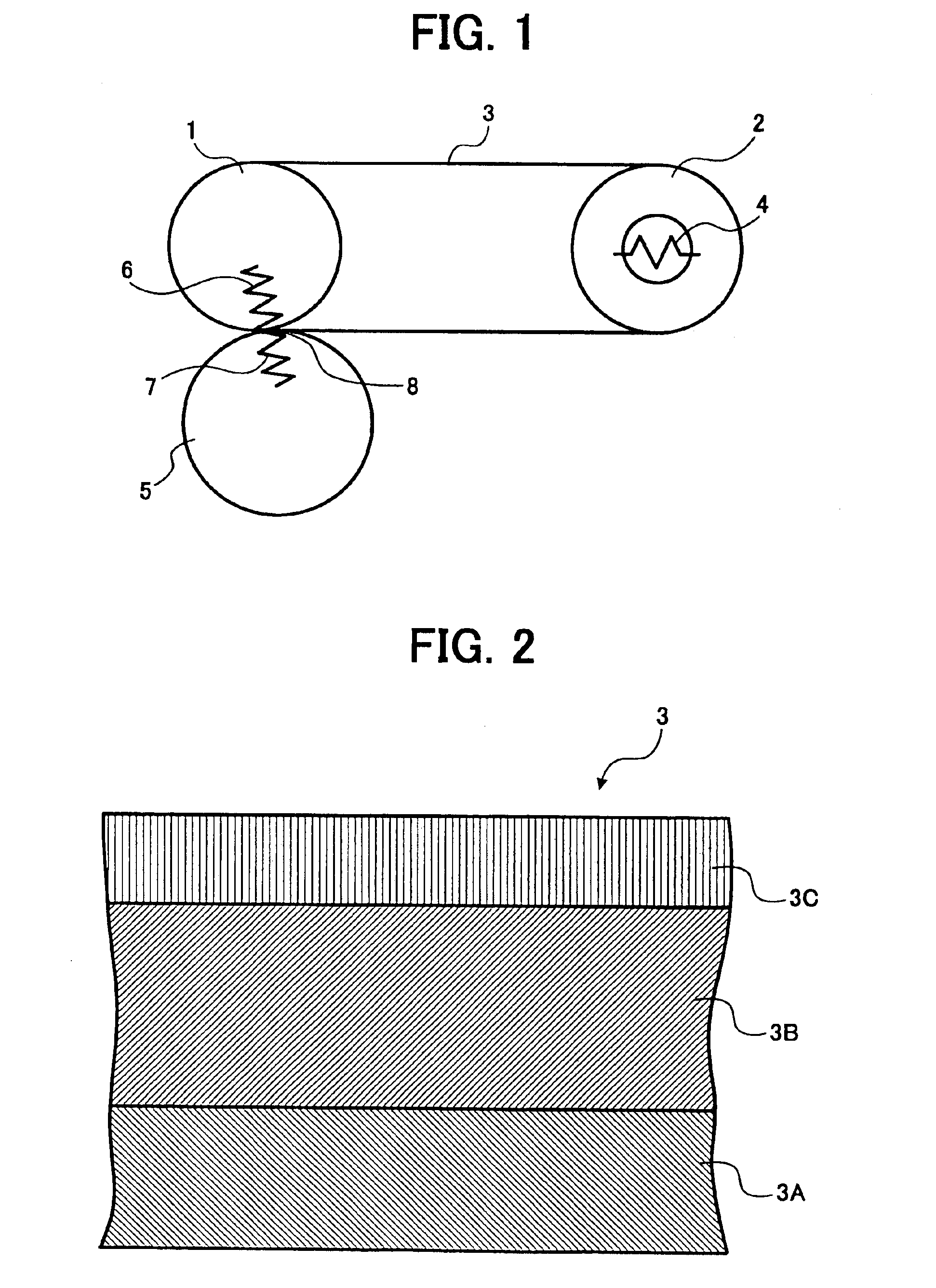

Image

  • Fixing belt and method for evaluating it
  • Fixing belt and method for evaluating it
  • Fixing belt and method for evaluating it

Examples


embodiment 1

[Embodiment 1]

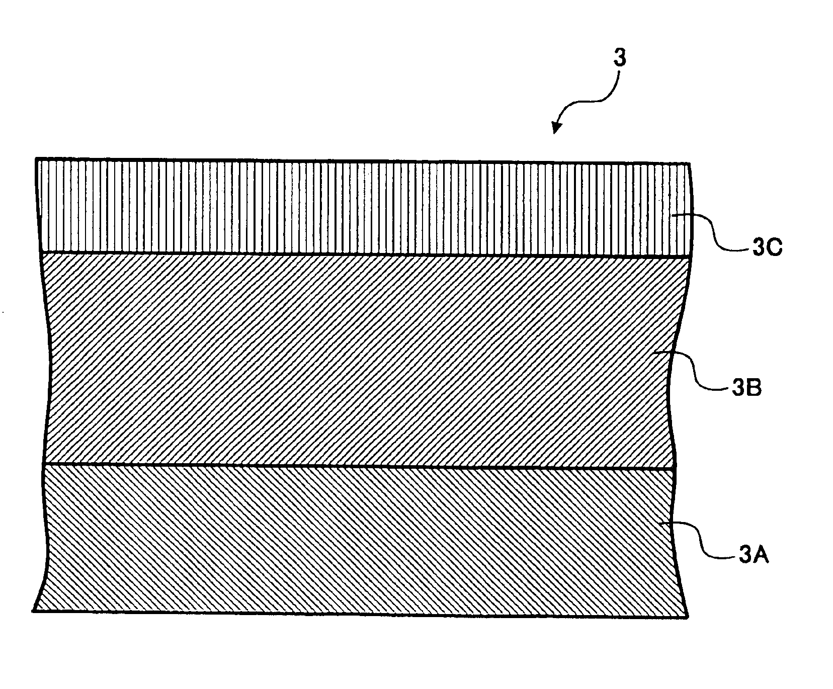
At first a plurality kind of triple layer fixing belt 3 which is composed of the substrate 3A, the elastic layer 3B and the mold releasing layer 3C, are prepared and creep values of the respective fixing belt 3 are measured and then an experiment whether or not an occurrence of crumple does occur on a paper is performed with loading the respective fixing belt 3 on a belt fixing device as well.

For example as one example of the fixing belt 3 a substrate 3A which is made of poly-imide resin and it has dimensions of 60 mm diameter, 315 mm length and 50 μm thickness, is prepared, and a silicon rubber (hardness 25 degree by JIS: Japanese Industrial Standard K 6301) layer having 200 μm thickness is formed as the elastic layer 3B on the substrate 3A, and FEP resin layer having 8 μm thickness is further formed as the mold releasing layer 3C on the elastic layer 3B and a test piece of the fixing belt is made. The creep value at the surface of this fixing belt 3 is examined and t...

embodiment 2

[Embodiment 2]

Secondly a creep value of the elastic layer 3B is measured to thereby observe a relation between the value and the occurrence of crumple about the elastic layer 3B which is formed on the substrate 3A as well. At this point the substrate a 3A and the elastic layers 3B are quite the same as prepared for the Embodiment 1 as described above.

As a result when they are compiled, it is found out that there is a tendency as shown in FIG. 5 between the creep values and the occurrences of crumples.

Judging from FIG. 5 it is found out that there is no occurrence of crumple on the material paper when the creep value CHU of the elastic layer 3B is included within a range B which is defined by a formula 0.05≦CHU≦0.80(%).

embodiment 3

[Embodiment 3]

Thirdly a creep value of the mold releasing layer 3C is measured to thereby observe a relation between the creep value and the occurrence of crumple on the material paper about the mold releasing layer 3C which is formed on the substrate 3A as well. At this point the substrates 3A and the mold releasing layers 3C are quite the same as prepared for the Embodiment 1 as described above.

As a result when they are compiled it is found out that there is a tendency as shown in FIG. 6 between the creep values and the occurrence of crumple.

Judging from FIG. 6 it is found out that there is no occurrence of crumple on the material paper when the creep value CHU of the mold releasing layer 3C is made within a range C which is defined by a formula 3.0≦CHU≦6.0(%).


PUM

PropertyMeasurementUnit
Fractionaaaaaaaaaa
Fractionaaaaaaaaaa
Fractionaaaaaaaaaa

Abstract

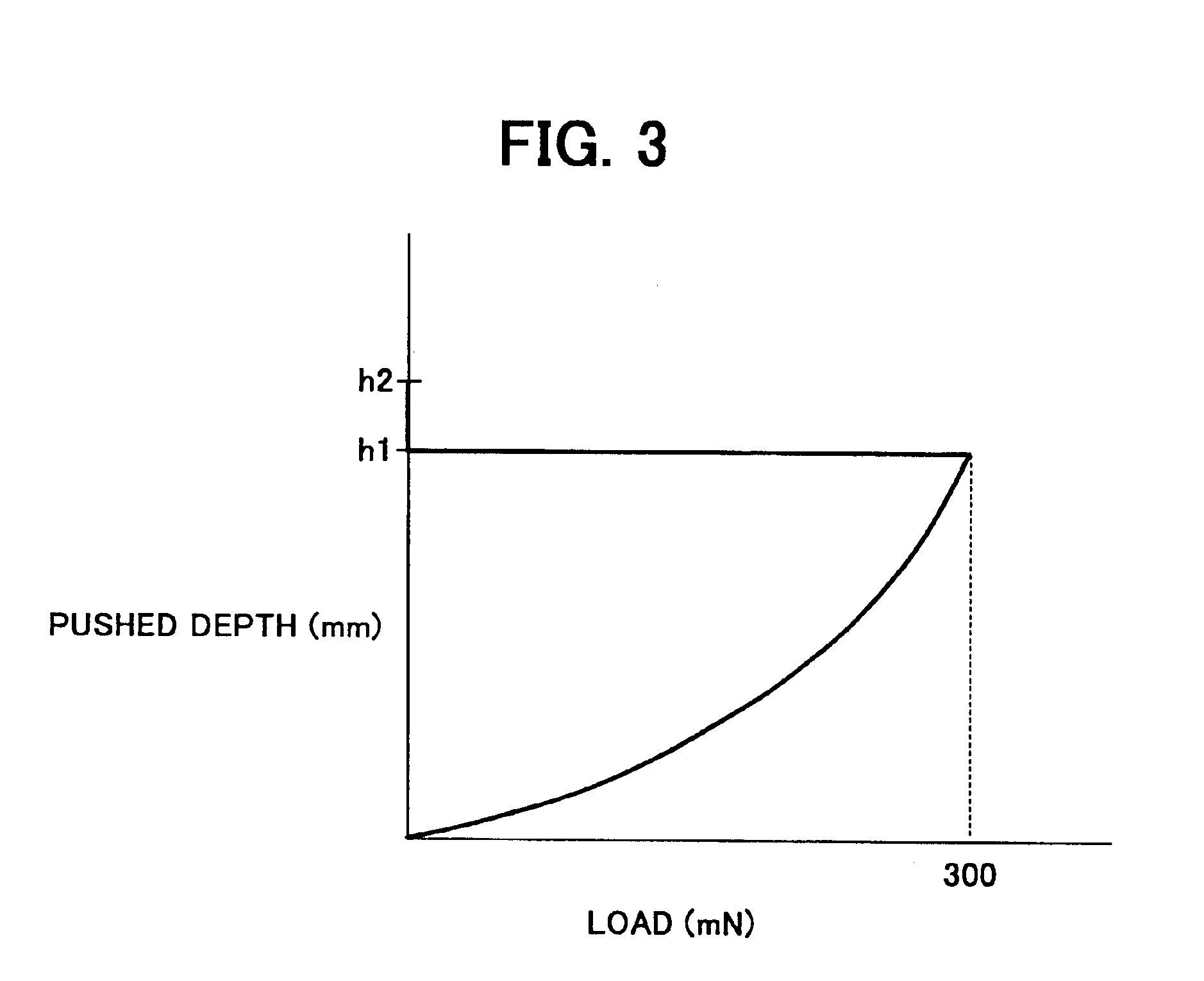
Disclosed are a fixing belt and a method for evaluating it in which an occurrence of crumple can be prevented by means of accurate evaluation whether a surface of the fixing belt has a appropriate flexibility or not.In this method for evaluating, a universal hardness test is achieved for the fixing belt in which an elastic layer and a mold releasing layer are laminated on a substrate, the fixing belt is judged as an acceptable product if a creep value CHU is included within a range of 0.40≦CHU≦3.50(%) when a creep value CHU which is measured from the mold releasing layer side is defined by a formula below.CHU=(h2−h1) / h1×100(%)where h1 is a pushed depth (mm) when a test load reaches a predetermined value which is kept for a predetermined period of time, andh2 is a pushed depth (mm) when a predetermined period of time is elapsed after the test load is removed.

Description

BACKGROUND OF THE INVENTION1. Field of the InventionThe present invention relates to a fixing belt which is utilized in an electro-photographic apparatus and the like and to a method for evaluating the fixing belt.2. Description of the Prior ArtIn general, there is an electro-photographic apparatus and the like in which a belt fixing device having a fixing belt utilized is equipped.As one example, such a belt-fixing device is disclosed in Japanese Patent Laid-Open Publication No. Hei 06-318001. The belt-fixing device disclosed in the publication is constituted so that it includes a fixing roller and a heating roller, and an endless like fixing belt having on a surface thereof a mold releasing layer is loaded between the both rollers, a pressure roller is disposed under the fixing roller to pinch the fixing belt to pass a paper through a nipping portion between the fixing belt and the nip roller.Further, the belt-fixing device is provided with a preheating process which is arranged b...

Claims


Application Information

Patent Timeline
IPC IPC(8): G03G15/20G01N3/00G01N3/02G01N3/40
CPCG03G15/2057G01N2203/0071G01N2203/0282G03G2215/2016Y10T428/24479Y10T428/24628Y10T428/24612Y10T428/24777G03G2215/2032
Inventor KAMIYA, KOHJIASHIKAWA, KYOICHIAZE, NORIHIKOMATSUO, MINORUTAKAHATA, NOZOMU
Owner RICOH KK
Learn More