High-luminosity EUV-source devices for use in extreme ultraviolet (soft X-ray) lithography systems and other EUV optical systems

a technology of euv source devices and optical systems, applied in the field of high-luminosity euv source devices for use in extreme ultraviolet (soft x-ray) lithography systems and other euv optical systems, can solve the problems of large amount of expense and effort, large amount of sr sources, and burdensome resolution limitations of optical (vuv) microlithography, and achieve the effect of increasing the usable quantity of ligh

Inactive Publication Date: 2005-03-01
NIKON CORP
View PDF6 Cites 28 Cited by
  • Summary
  • Abstract
  • Description
  • Claims
  • Application Information

AI Technical Summary

Problems solved by technology

In this regard, the resolution limitations of optical (VUV) microlithography have become burdensome, resulting in an extensive current effort to develop a practical “next generation lithography” (NGL) system.
An especially large amount of expense and effort has been directed to the development of a practical SXR (EUV) microlithography system that utilizes an exposure wavelength in the range of 10-15 nm.
However, SR sources are extremely large and expensive and provide EUV light intensity that is too low for practical use in lithography.
If etendue were allowed to increase above this limit, it theoretically would become impossible to guide such a beam to an illumination region.
The maximum output from a discharge-plasma EUV source is limited mainly by the thermal-load limit of the source.
In addition, since the plasma is generated in the vicinity of the electrodes, heat from the plasma also is transmitted by irradiation to the electrodes, which further increases the heat load on the electrodes.
This inability to dissipate heat from the electrodes causes further heat accumulation in the electrodes.
Under such conditions the temperature increase can be sufficiently high to melt the electrodes, rendering plasma (and thus EUV) generation impossible.
However, as shown in FIG. 2, merely bundling multiple sources 7 in this manner increases the effective width of the collective light source to an extent that the etendue of EUV light produced by the bundled source is too large for effective utilization of the EUV beam from the source.
As a result, with the conventional bundled source, the output of EUV light that actually can be used is insignificantly increased over that of an individual source.

Method used


Image

  • High-luminosity EUV-source devices for use in extreme ultraviolet (soft X-ray) lithography systems and other EUV optical systems
  • High-luminosity EUV-source devices for use in extreme ultraviolet (soft X-ray) lithography systems and other EUV optical systems
  • High-luminosity EUV-source devices for use in extreme ultraviolet (soft X-ray) lithography systems and other EUV optical systems

Examples


Embodiment Construction

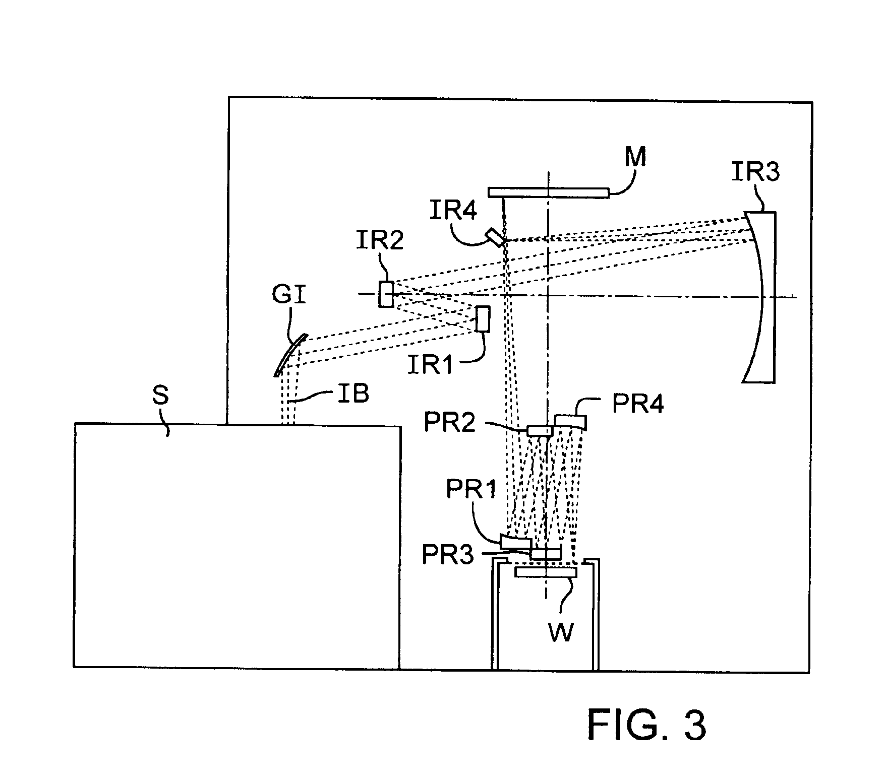
A schematic optical diagram of an embodiment of an X-ray microlithography system that utilizes a soft X-ray (SXR or EUV) source device S is shown in FIG. 3. The depicted system comprises the EUV-source device S, an illumination-optical system, a reticle stage (not shown but well-understood in the art) for holding a reticle M, a projection-optical system, and a substrate stage (not shown but well-understood in the art) for holding a substrate W (e.g., semiconductor wafer). The SXR-source apparatus generates an illumination beam IB of SXR (EUV) light.

The illumination beam IB propagates to the illumination-optical system comprising mirrors GI, IR1, IR2, IR3, IR4. The mirror GI usually is a grazing-incidence mirror that reflects the grazing-incident illumination beam IB from the source apparatus S. (Alternatively, the mirror GI can be a multilayer-film mirror.) The mirrors IR1, IR2, IR3, IR4 are multilayer-film mirrors each including a surficial multilayer film exhibiting high reflectiv...


PUM

PropertyMeasurementUnit
exposure wavelengthaaaaaaaaaa
diameteraaaaaaaaaa
diameteraaaaaaaaaa

Abstract

Devices and methods are disclosed that provide effective utilization of light beams produced from multiple EUV-light sources, especially such sources that have been bundled. An embodiment of an EUV-source device comprises multiple individual EUV-light sources each providing a respective point-light source of EUV radiation propagating as a respective beam from each point-light source. A reflective focusing-optical system is situated downstream of the EUV-light sources, and is configured to focus the beams from the point-light sources at a focus point. A variable-angle mirror is situated downstream of the focusing-optical system and is configured to reflect light of the respective beams from the point-light sources that has been reflected by the focusing-optical system. A mirror-tilting mechanism is coupled to the variable-angle mirror. The mechanism, when activated, tilts the mirror by a respective angle corresponding to the particular beam from one of the point-light sources that is incident on the mirror. This produces a composite beam propagating in a constant direction from the variable-angle mirror.

Description

FIELDThis disclosure pertains to sources of “soft X-ray” (SXR; also termed “extreme ultraviolet” or EUV) light. This disclosure also pertains to optical systems that include such sources, and to apparatus and systems including such optical systems, such as EUV lithography (EUVL) systems, SXR microscopes, and SXR analysis apparatus.BACKGROUNDIn recent years, with the incessant demand for increasingly smaller active circuit elements in semiconductor integrated circuits and other microelectronic devices, there has been an urgent demand for projection-microlithography systems capable of achieving pattern transfer with increasingly greater resolution of fine circuit patterns. In this regard, the resolution limitations of optical (VUV) microlithography have become burdensome, resulting in an extensive current effort to develop a practical “next generation lithography” (NGL) system. Promising NGL approaches are directed to the use of wavelengths substantially shorter than VUV, namely the X...

Claims


Application Information

Patent Timeline
Patent Type & Authority Patents(United States)
IPC IPC(8): G03F7/20G21K1/06G21K5/02H01L21/027H05G2/00
CPCB82Y10/00G03F7/70058G03F7/7005G03F7/70033H01L21/027
Inventor MURAKAMI, KATSUHIKO
Owner NIKON CORP
Why Eureka
Try Eureka