Organic electroluminescent display device driving method and apparatus

a technology of electroluminescent display device and driving method, which is applied in the direction of electrical apparatus, semiconductor devices, instruments, etc., can solve the problems of difficult to drive using simple two-terminal schemes, difficult to achieve in a fabrication process, and new problems in manufacturing are created

Inactive Publication Date: 2005-03-01
FPD SYST +1
View PDF11 Cites 43 Cited by
  • Summary
  • Abstract
  • Description
  • Claims
  • Application Information

AI Technical Summary

Problems solved by technology

A drawback with organic EL devices is that they are difficult to drive using simple two-terminal schemes because of their lack of memory.
While successfully overcoming the above-mentioned problem, new problems in manufacturing are created.
The storage capacitor process and deposition are very complicated and difficult to achieve in a fabrication process.
The TFTs fabrication requires several mask steps whose difficulty and cost increase dynamically as the display size increases.
Plus if the substrate is plastic an expensive laser annealing process is used in fabrication of the TFT.

Method used


Image

  • Organic electroluminescent display device driving method and apparatus
  • Organic electroluminescent display device driving method and apparatus
  • Organic electroluminescent display device driving method and apparatus

Examples


Embodiment Construction

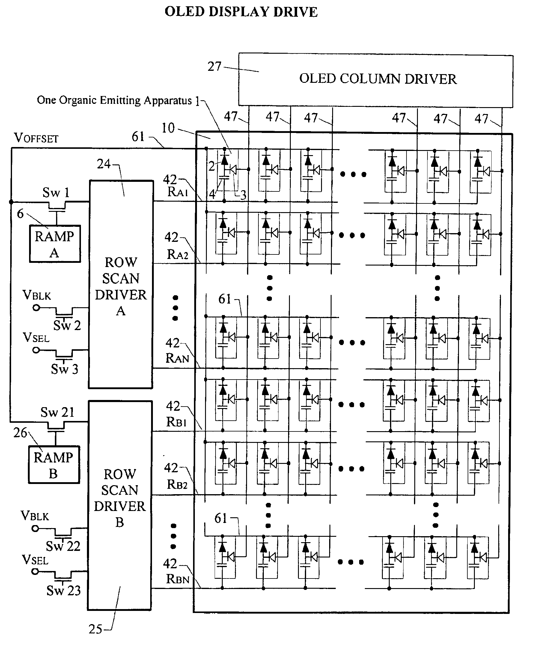
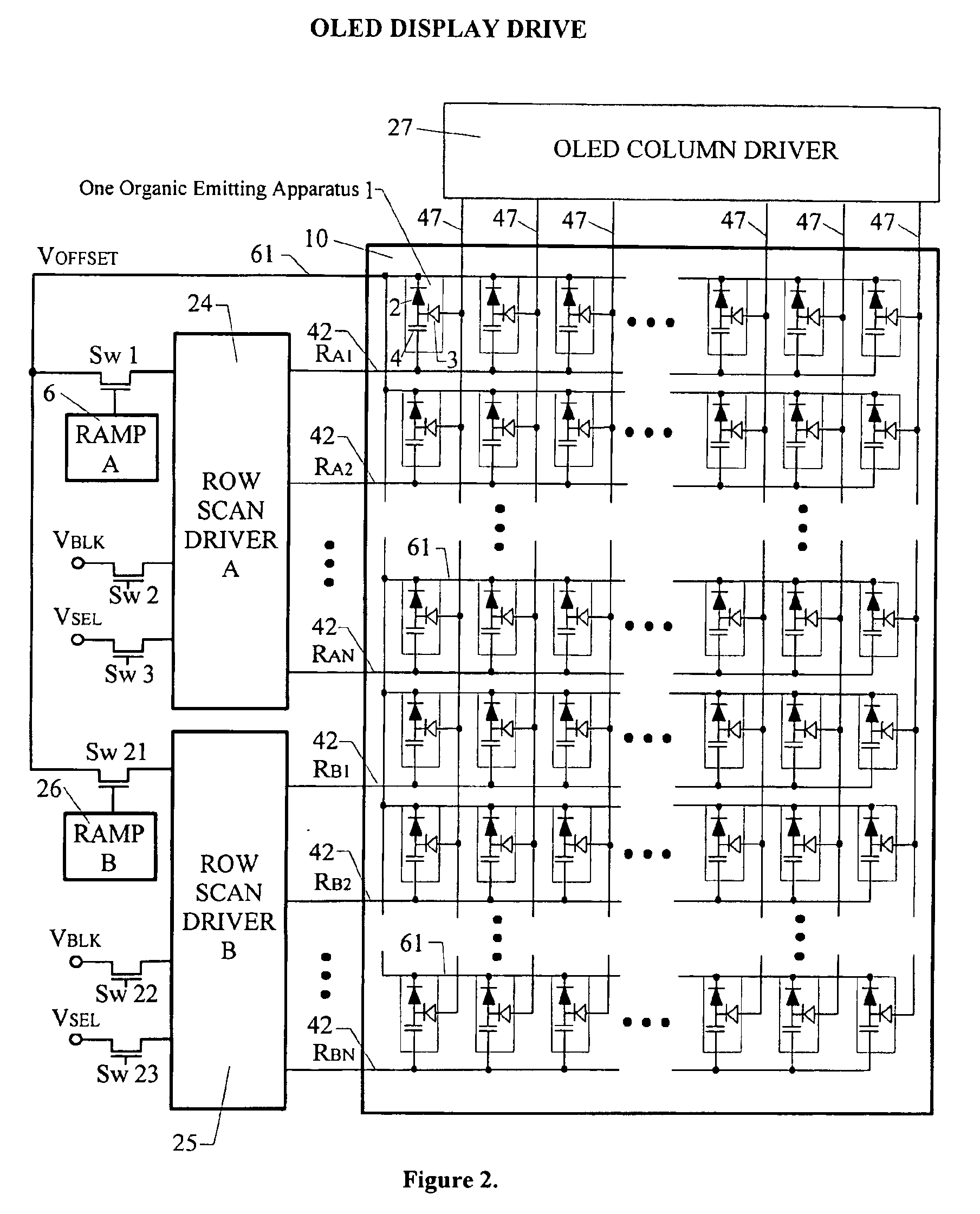
An organic light emitting diode display drive is illustrated in FIG. 2. As shown in FIG. 2, each organic emitting apparatus 1 consists of an organic light emitting diode 2, a rectification diode 3 and a memory capacitor 4. The charge stored in the capacitor during its addressing period is discharged through the light emitting diode during the light output period. To be able to take advantage of existing row scan driver ICs an Address Display Together (ADT) scheme is used. For example while Row Scan Driver A 24 is selecting rows (address period), Row Scan Driver B 25 has a ramp voltage output (light output period). The OLED Column Driver 27 IC's exceptionally tight current matching of adjacent outputs ensures uniform luminance and high-quality gray scaling. For color displays the column electrodes are in a RGB pattern and the current source magnitude of each color can be set independently. This makes possible for a white balance of the display.

As shown in FIG. 2 the display 10 is an ...


PUM


Abstract

The object of the invention is to provide an organic electroluminescent display device and driving method including an apparatus comprised of at least one organic-light-emitting diode (OLED), a rectification diode and a capacitor used as a memory device. A frame period of the display device is divided into sub-frames, which have address and light emission periods. Current mode data programming is used to address the display device in each sub-frame. In the light emission period, charge previously stored in selected capacitors during the address period, supplies the forward current for the OLEDs. A ramp waveform applied to the row electrode, during the light emission period, forces the capacitor to discharge through the OLED and controls the forward current level. The operation of the OLEDs are retained in their area of maximum performance.

Description

FIELD OF THE INVENTIONThe present invention relates generally to an organic EL (electroluminescent) device and more specifically to a driving method and apparatus for such a device.BACKGROUND OF THE INVENTIONThere are two types of organic EL display devices, a passive (a simple matrix) and an active (an active matrix), and development of both is being enthusiastically performed. Furthermore, organic materials are divided into low molecular weight (monomer) organic EL materials and high molecular weight (polymer) organic EL materials. Both are being vigorously researched, where a film of low molecular weight organic EL material is mainly formed by evaporation, while a film of high polymer organic EL material is mainly formed by application.A drawback with organic EL devices is that they are difficult to drive using simple two-terminal schemes because of their lack of memory. The rise and decay time of an organic EL device is very fast and it does not have intrinsic memory. To overcom...

Claims


Application Information

Patent Timeline
Patent Type & Authority Patents(United States)
IPC IPC(8): G09G3/32H01L27/32H01L27/28G09G3/20
CPCG09G3/3241G09G3/2014G09G3/2025G09G3/3266G09G2300/0452G09G2300/0842H01L27/3244G09G2300/088G09G2310/0221G09G2310/0259G09G2310/066H01L27/3211G09G2300/0861H10K59/35H10K59/12
Inventor RUTHERFORD, JAMES C.
Owner FPD SYST
Why Eureka
Try Eureka