Switching power supply circuit

a power supply circuit and switching converter technology, applied in the direction of electric variable regulation, process and machine control, instruments, etc., can solve the problems of high generation level of noise, damage to power factor indicative of power supply utilization efficiency, and inability to ignore the switching noise of the converter, so as to reduce the number of switching converter sections, reduce the number of parts, and reduce the effect of size and weigh

Inactive Publication Date: 2006-08-31
SONY CORP
View PDF10 Cites 54 Cited by
  • Summary
  • Abstract
  • Description
  • Claims
  • Application Information

AI Technical Summary

Benefits of technology

[0149] From this, the present invention adopts a configuration that a switching power supply circuit ready for a wide range including a power factor improving function does not include an active filter. Consequently, the switching power supply circuit has an effect that the power conversion efficiency is improved when compared with an alternative case wherein it is tried to improve the power factor, for example, by means of an active filter.
[0150] Further, the switching power supply circuit of the present invention eliminates the necessity for a large number of part elements for configuring an active filter. Further, since the current resonance type converter and the power factor improving circuit which configure the power supply circuit perform soft switching operation and the switching noise is reduced significantly, also the necessity for reinforcing a noise filter is eliminated.
[0151] Therefore, when compared with the related art, the number of parts is reduced significantly, and consequently, reduction in size / weight of the power supply circuit can be anticipated. Also the cost can be reduced as much.
[0152] While the switching power supply circuit according to the present invention is particularly ready for a heavy load condition, since an active filter which is ready for a heavy load requires a greater number of parts, the effect of reduction in size and weight and reduction of the cost of the circuit is very effective.
[0153] Furthermore, since the active filter is eliminated, the interference between the ground potentials on the primary side and the secondary side is eliminated, the ground potential is stabilized and the reliability is enhanced.
[0155] In contrast, according to the present invention, the switching power supply circuit includes a switch section to make it possible to successively start a plurality of secondary side DC voltages while the starting timings are controlled. Consequently, the necessity for the provision of a number of switching converter sections equal to the number of stages at which the secondary side DC output voltages are to be started is eliminated, and as occasion demands, the number of switching converter sections can be reduced when compared with that of the related art. Also by this, reduction of the number of part elements and resulting reduction in size and weight as well as reduction of the cost can be anticipated, and also reduction of the switching loss can be anticipated as a result of the reduction of the number of switching converter sections.

Problems solved by technology

Incidentally, generally if commercial power supply is rectified, then since current flowing through a smoothing circuit is distorted in waveform, there is a problem that the power factor indicative of the utilization efficiency of power supply is damaged.
However, the power supply circuit having the configuration shown in FIG. 11 has the following problem.
Further, while, in the active filter circuit 8, switching operation as a step-up type converter is performed, since the switching operation depends upon dv / di and di / dt and is hard switching operation, the generation level of noise is very high.
Further, since three composite resonance type converters and two step-down type converts are provided at the next stage to the active filter, also switching noise of them is so high that it cannot be ignored.
Particularly since the step-down type converters perform hard switching operation, the amount of switching noise generation is great.
In contrast, although the composite resonance type converters perform soft switching operation and generates switching noise of a smaller amount than the hard switching converters, since the arrangement includes three composite resonance type converters, the overall noise amount is great as much.
In this manner, in an actual circuit, a countermeasure against noise based on a very large number of parts is required, and this gives right to increase of the cost and increase of the mounting area of the power supply circuit board.
Where the switching frequencies of the switching converters are different from each other in this manner, there is a problem also that the ground potentials of the primary side and the secondary side interfere with each other and the operation of the power supply circuit is liable to be rendered unstable.
This gives rise to a disadvantage that, if it is tried to cope with an increase of the number of stages of a starting sequence of secondary side DC output voltages, then the number of converter sections increases only for this, and as a result, the number of components of the converter sections beginning with a control IC, an insulating converter transformer PIT, a switching element and so forth increases exceeding a necessary number.
Such increase of the number of converter sections is not preferable because it results in increase in size and weight of a power supply circuit board.
Further, where the converter sections increase, also the switching loss of the primary side switching elements increases correspondingly, and this is disadvantageous also in power conversion efficiency.

Method used


Image

  • Switching power supply circuit
  • Switching power supply circuit
  • Switching power supply circuit

Examples


first embodiment

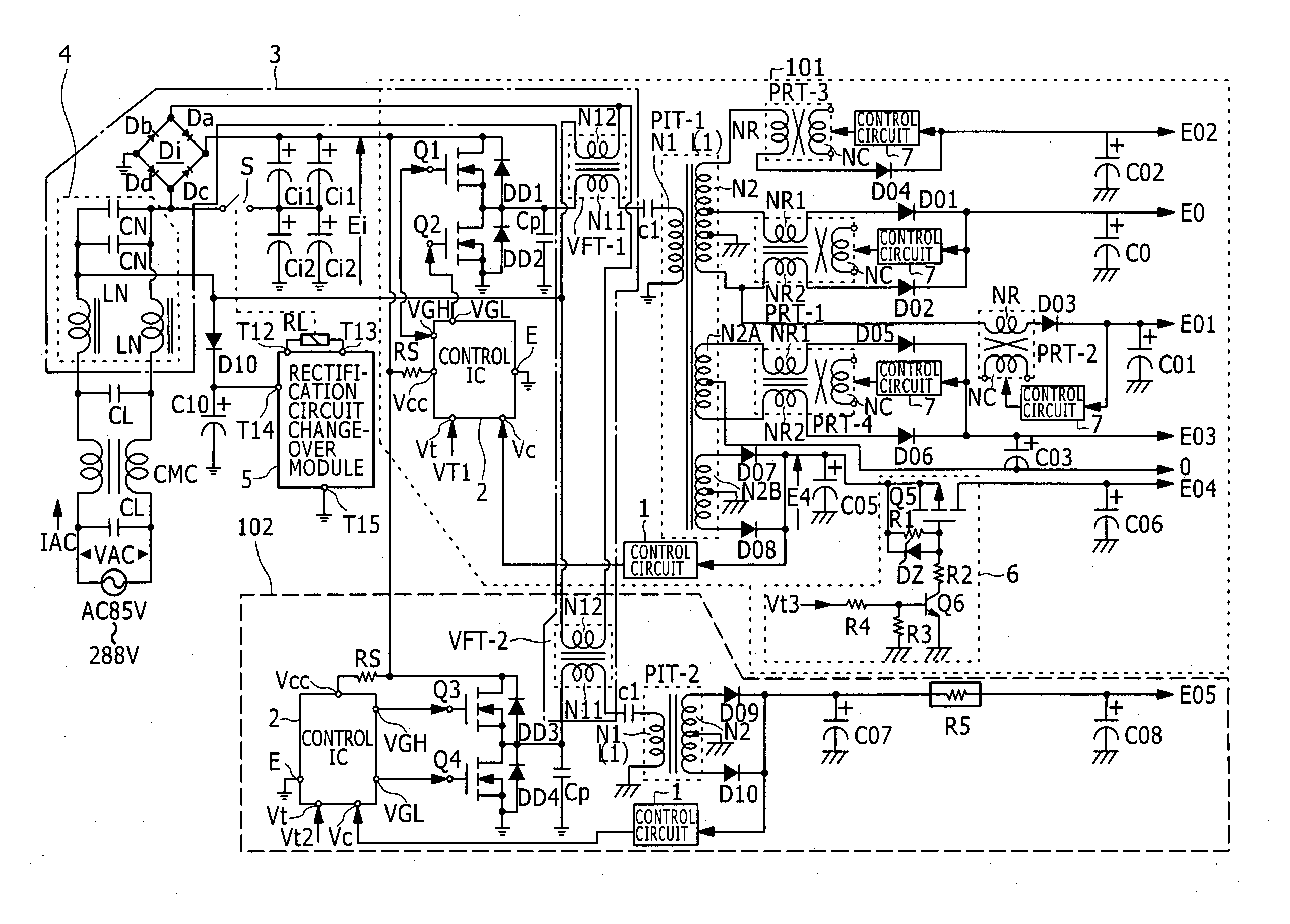
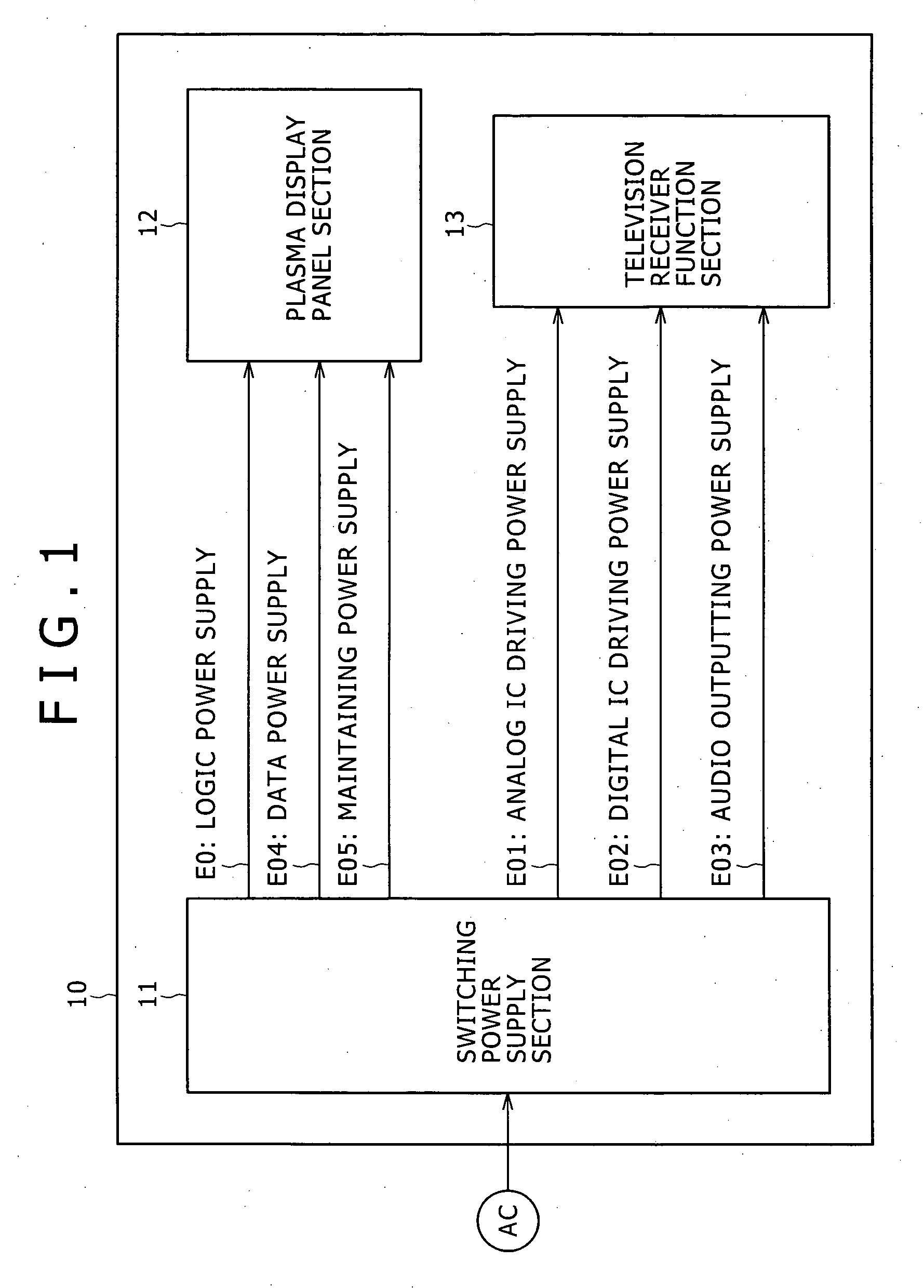
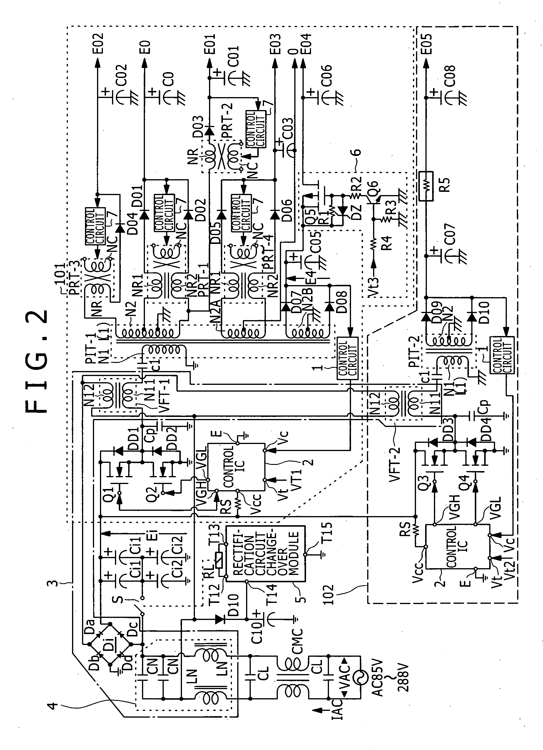
[0187]FIG. 2 shows an example of a configuration of a switching power supply circuit of the present invention as a switching power supply circuit which can be applied to the switching power supply circuit 11 shown in FIG. 1. The power supply circuit shown in FIG. 2 adopts a configuration which can be ready for the load power Po=600 W or more and operates with the AC 100 V system and the AC 200 V system of commercial AC power supply so that it is ready for a wide range.

[0188] In particular, the plasma display apparatus 10 as the present embodiment has so-called worldwide specifications such that it can operate in both of regions of the AC 100 V system of commercial power supply such as, for example, Japan and the United States and regions of the AC 200 V system such as Europe. Further, the power specification of the entire plasma display apparatus is generally 600 W or more.

[0189] In the power supply circuit shown in FIG. 2, a line filter formed from one common mode choke coil CMC a...

second embodiment

[0340]FIG. 6 shows an example of a configuration of a switching power supply circuit as a It is to be noted that, in FIG. 6, like elements to those of FIG. 2 are denoted by like reference characters and description thereof is omitted herein.

[0341] In the power supply circuit shown in FIG. 6, firstly the internal configuration of the DC switch circuit (switch section) 6 provided on the first converter section 101 side is different from that in the case of FIG. 2. In particular, the DC switch circuit 6 includes a time constant capacitor C3. The power factor improving circuit 3 in this instance is formed from, for example, an electrolytic capacitor, and is connected at the positive terminal thereof to the base of the bipolar transistor Q6 and at the negative terminal thereof to the secondary side ground.

[0342] Further, in this instance, as an on / off control signal to be inputted to the DC switch circuit 6, the secondary side DC output voltage Eo5 of the second converter section 102 i...


PUM


Abstract

A switching power supply circuit ready for a wide range and including a power factor improving function is disclosed which can achieve reduction in cost, reduction in size and weight of the circuit and reduction of the power loss by reducing the number of converter sections with respect to the number of stages in a starting order of secondary side DC output voltages. A plurality of switching converters (101), (102) are of the composite resonance type wherein a partial resonance voltage circuit is combined with a switching converter of the current resonance type according to a half-bridge connection system. Changeover control is performed such that a rectification circuit serves as a voltage doubler rectification circuit at an AC voltage equal to or lower than 150 V, but serves as a full-wave rectification circuit at another AC voltage equal to or higher than 150 V. Power factor improvement is implemented by feeding back the voltages of outputs of the converters to a rectification current path by a power factor improving transformer (VFT) and interrupting the rectification current by means of a rectification diode to expand the

Description

TECHNICAL FIELD [0001] This invention relates to a switching power supply circuit including a circuit for the power factor improvement, and a plasma display apparatus which incorporates the switching power supply circuit. BACKGROUND ART [0002] In recent years, since switching elements which can withstand comparatively high current and voltage of a high frequency have been developed, most of power supply circuits which rectify commercial power supply to obtain a desired DC voltage are formed as power supply circuits of the switching type. [0003] A switching power supply circuit reduces the size of transformers and other devices by using a high switching frequency and is used as a high-power DC-DC converter and as a power supply for various kinds of electronic apparatus. [0004] Incidentally, generally if commercial power supply is rectified, then since current flowing through a smoothing circuit is distorted in waveform, there is a problem that the power factor indicative of the utili...

Claims


Application Information

Patent Timeline
Patent Type & Authority Applications(United States)
IPC IPC(8): G09G5/00H02M1/10H02M3/28H02M7/12H02M3/335
CPCH02M1/10H02M1/4258H02M3/33561Y02B70/126Y02B70/10H02M3/28H02M7/12
Inventor YASUMURA, MASAYUKI
Owner SONY CORP
Why Eureka
Try Eureka