Voltage down converter for low voltage operation

a voltage converter and low voltage technology, applied in the field of voltage converters, can solve problems such as limitation of circuit fig. 1, and achieve the effect of stable operation and high gain

Inactive Publication Date: 2005-03-01
POLARIS INNOVATIONS LTD
View PDF2 Cites 17 Cited by
  • Summary
  • Abstract
  • Description
  • Claims
  • Application Information

AI Technical Summary

Benefits of technology

[0009]The present invention is directed to a novel voltage down converter for a memory chip that provides a more stable operation in situations where the value of the external voltage Vext is low. In accordance with the invention, a voltage down converter is provided in which there is a dual source follower between the reference voltage generator and the (operational amplifier) comparator. The dual source follower has two sections whose inputs are cross-coupled so that the sections conduct in opposite directions. The reference voltage generator supplies the reference voltage Vintref to one input of each of the two follower sections and the output voltage Vint of the pull up transistor is applied to the other input of each follower section. Each follower section produces an output voltage that is the difference between the input voltages Vintref and Vint but the outputs of the two sections are in opposite directions.
[0011]Accordingly, the present invention solves the problem by the dual source follower shifting the input voltage difference between Vintref and Vint to another voltage difference which can be more easily amplified by the comparator. In accordance with the invention, the voltage gain of the dual source follower is greater than 1.0 and the comparator 20 can amplify the shifted voltage difference with high sensitivity.

Problems solved by technology

Therefore, the circuit of FIG. 1 has a limitation in the case where it has to regulate a value of Vint that is close to the external voltage Vext level, such as low voltage applications require.

Method used


Image

  • Voltage down converter for low voltage operation
  • Voltage down converter for low voltage operation
  • Voltage down converter for low voltage operation

Examples


Embodiment Construction

converter of FIG. 1.

[0015]FIG. 2 is a diagram of the voltage down converter of the invention;

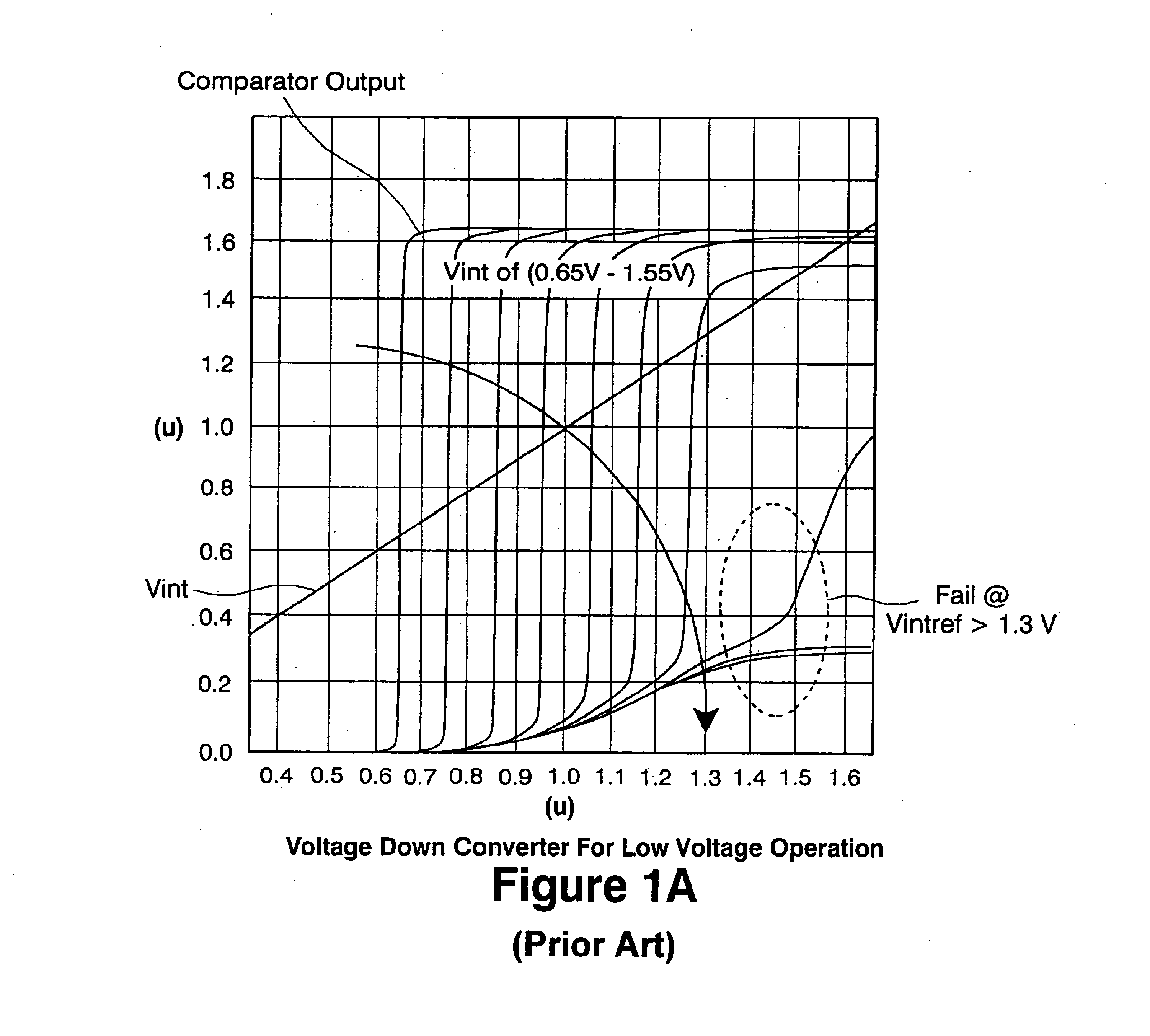
[0016]FIG. 2A is a diagram illustrating the operation of the circuit of FIG. 2; and

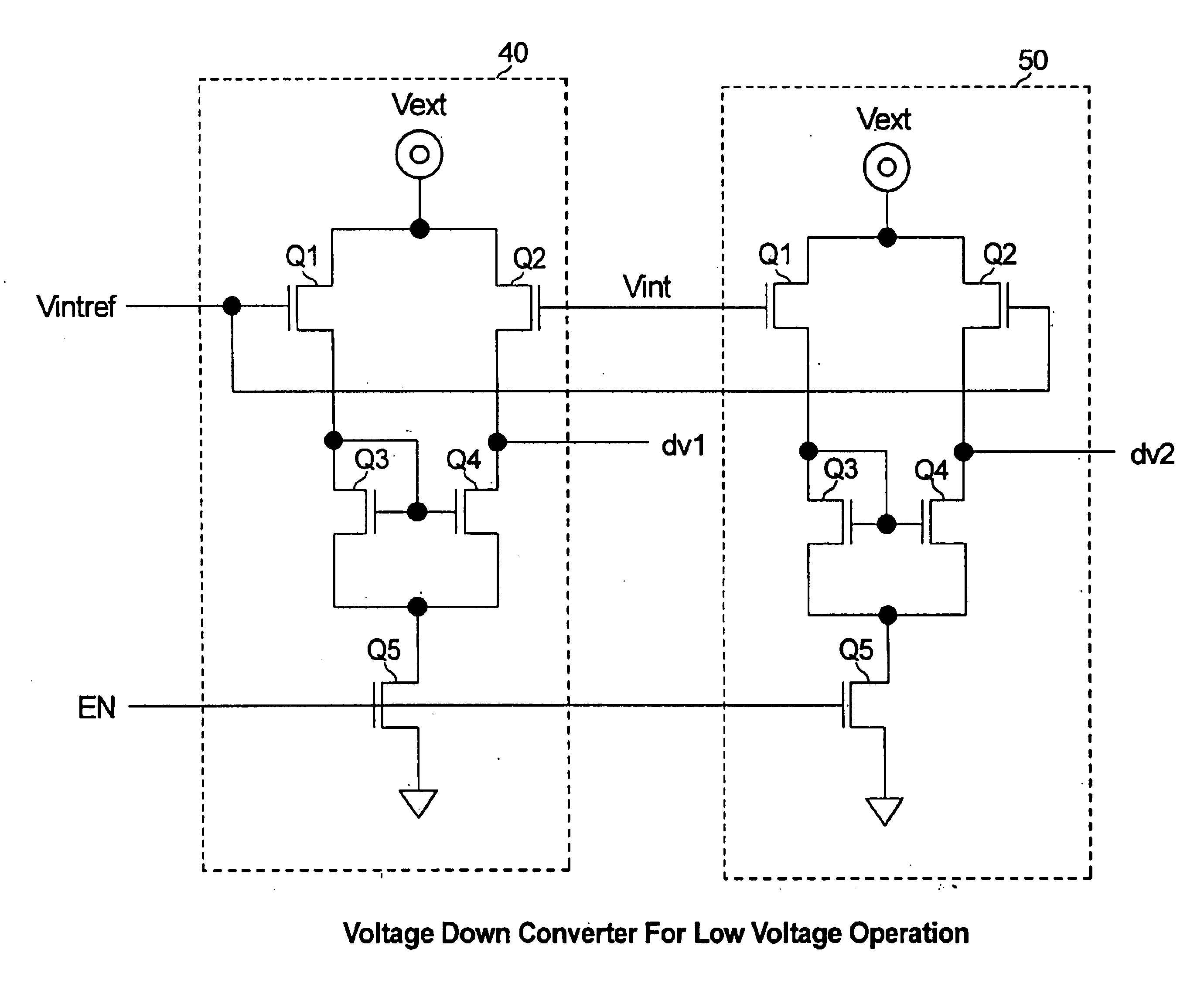
[0017]FIG. 3 is a schematic diagram of the dual source follower circuits in accordance with the present invention.

DETAILED DESCRIPTION OF THE INVENTION

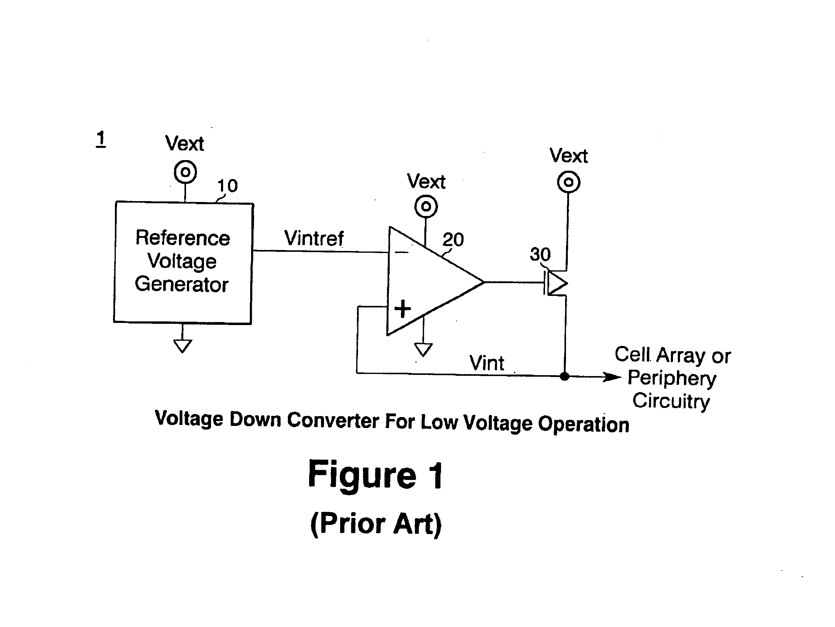
[0018]Referring to FIG. 2, the voltage down converter of the invention has on the memory chip the reference voltage generator 10, comparator 20 and PMOS transistor pull up driver 30, as previously described. Here, the output Vintref of the reference voltage generator 10 is applied to the opposite polarity inputs of two source voltage followers 40 and 50. The source followers 40 and 50 have the same construction and are described in detail below. That is, the Vintref voltage is applied to negative (−) input of source follower 40 and to the positive (+) input of source follower 50. The output voltage Vint from the pull up transistor 30 is applied to the (+) input ...


PUM


Abstract

A voltage down converter for a semiconductor memory device to convert an external voltage to a lower value internal voltage for the device, has a voltage generator that produces a reference voltage corresponding to the value of the internal voltage, a comparator having opposite polarity inputs for producing an amplified output control signal, and a pull-up device operating from the external voltage that receives the control signal from the comparator to produce the internal voltage as an input. A dual source follower is located between the reference voltage generator and comparator and has two sections having cross-coupled inputs which respectively receive the internal reference voltage and the internal voltage to produce output voltages moving in opposite directions, each of which is applied to one input of the comparator, thereby translating the difference between Vintref and Vint to a level in a range that can be better amplified by the comparator.

Description

FIELD OF THE INVENTION[0002]The present invention relates to a voltage down converter for semiconductor memory devices, such as synchronous DRAM, SRAM and other memory devices which operate from a very low value external voltage.DESCRIPTION OF THE PRIOR ART[0003]Semiconductor memory circuits are well integrated circuit devices, often called a memory chip. In general, memory circuits such as synchronous DRAM operate from a very low value external voltage as a power supply. This is particularly true for such memory devices used in mobile applications, such as hand-held and laptop computers. A voltage down converter is usually provided as an integral part of the memory device circuitry. The voltage down converter reduces the value of the power supply voltage Vext of the external source, such as a battery, to a lower voltage Vint that is used to supply voltage to the memory cells and other peripheral circuits of the device. A typical value of Vext would be 1.8 volts and for Vint would b...

Claims


Application Information

Patent Timeline
Patent Type & Authority Patents(United States)
IPC IPC(8): H03K19/0185H04L25/02
CPCH03K19/018578
Inventor SUH, JUNGWON
Owner POLARIS INNOVATIONS LTD
Why Eureka
Try Eureka