Circuits with dynamic biasing

a dynamic biasing and circuit technology, applied in pulse manipulation, frequency selective two-port network, pulse technique, etc., can solve the problem that biases can, in some cases, interact with signals, and achieve the effect of avoiding excessive interaction and high signal-to-noise ratio

Inactive Publication Date: 2005-03-01
THE TRUSTEES OF COLUMBIA UNIV IN THE CITY OF NEW YORK
View PDF16 Cites 11 Cited by
  • Summary
  • Abstract
  • Description
  • Claims
  • Application Information

AI Technical Summary

Benefits of technology

It is a further object of the invention to provide a circuit which can accommodate signals of various amplitudes while maintaining a high signal-to-noise ratio.
It is yet another object of the invention to provide a circuit which can accommodate signals of various amplitudes while avoiding excessive interaction between the bias control and the signal.

Problems solved by technology

However, one potential problem is that the bias can, in some cases, interact with the signal.

Method used


Image

  • Circuits with dynamic biasing
  • Circuits with dynamic biasing
  • Circuits with dynamic biasing

Examples


Embodiment Construction

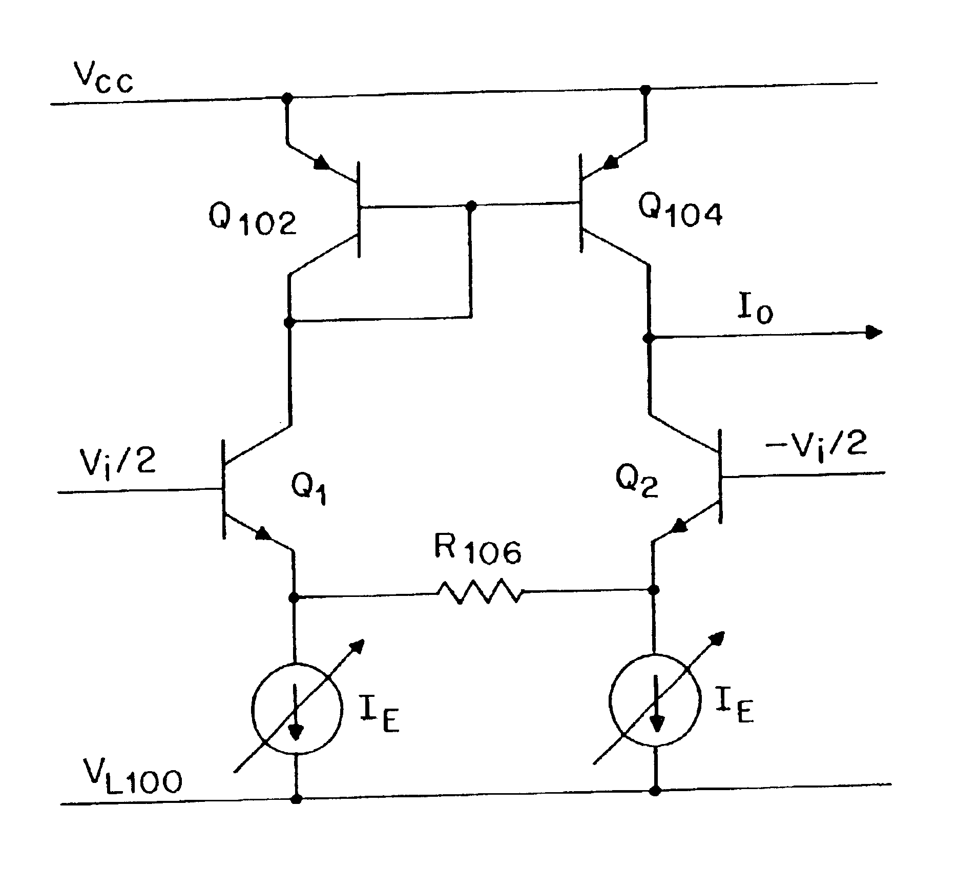
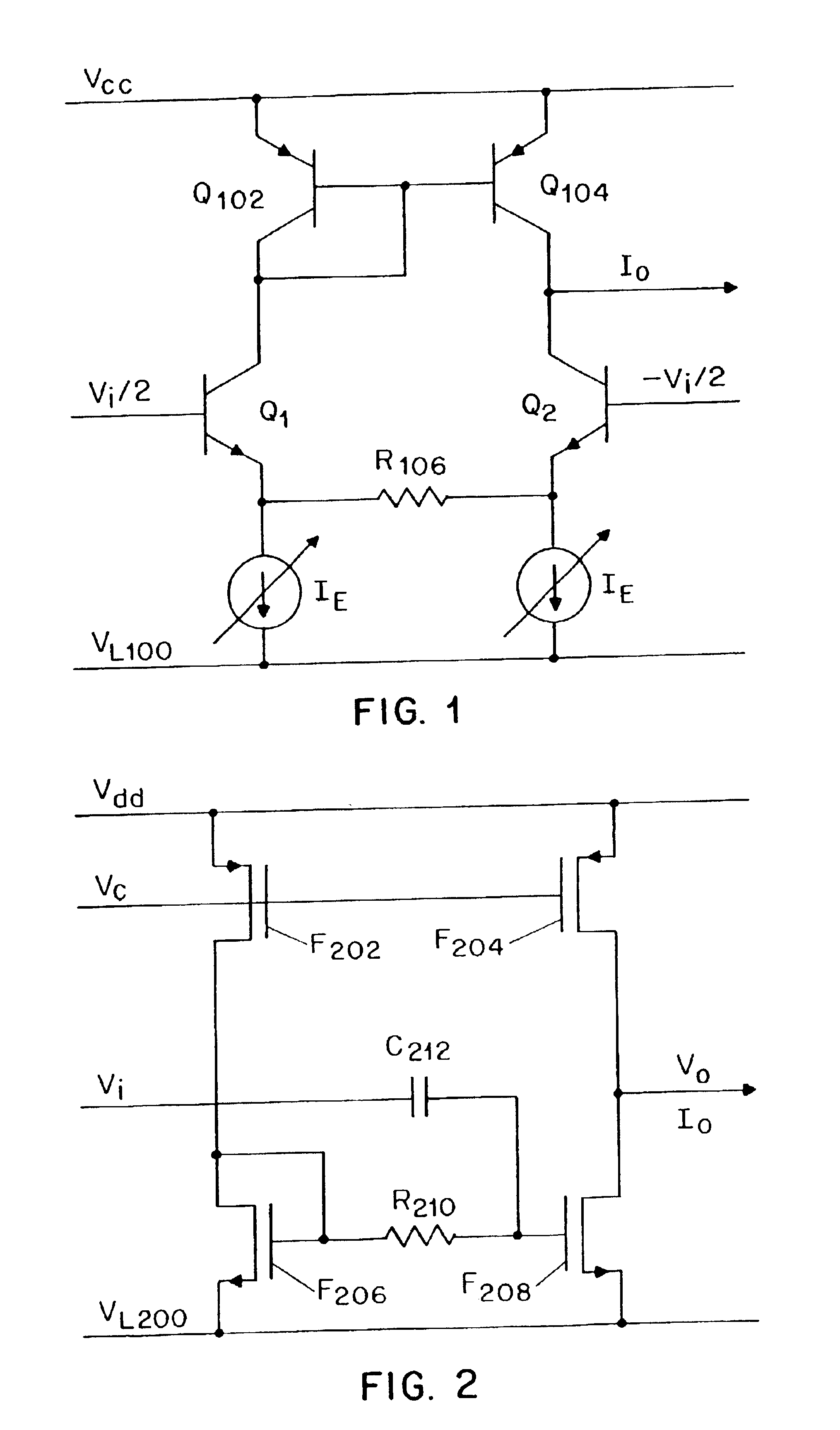
FIG. 1 illustrates an example of a transconductor circuit which is dynamically biased in accordance with the invention. The circuit of FIG. 1 is powered by voltage sources VCC and VL100. It is to be noted that voltage (i.e., electrical potential) is inherently relative, and accordingly, the term “voltage source,” as used herein, is defined to include ground (i.e., a voltage source producing a voltage of zero). In particular, in the circuit of FIG. 1, either of VCC and VL100 can be a connection to ground. The same is true for at least one voltage source in each of the circuits disclosed herein.

In the circuit of FIG. 1, transistors Q102 and Q104 form a current mirror which sends current through transistors Q1 and Q2, respectively. The emitters of transistors Q1 and Q2 are connected by a resistor R106. Each of transistors Q1 and Q2 is biased with a bias current IE which flows through its current-carrying terminals—specifically its emitter and collector. The transconductor of FIG. 1 is ...


PUM


Abstract

Techniques are provided for the implementation of dynamically biased circuits. In these circuits, bias currents are varied according to signal amplitude. Benefits include reduced power dissipation, reduced noise, and increased dynamic range. The techniques can be employed in various types of circuits such as, for example, amplifiers, log-domain circuits, and filters.

Description

BACKGROUND OF THE INVENTIONIn order to conserve energy in electronic circuits, particularly in battery-operated electronics, it is preferable to use bias currents which are no larger than necessary. Therefore, because the minimum required bias current tends to depend on signal amplitude, it is often desirable to use actual bias currents which are dependent on the amplitude of the signal. An additional advantage of amplitude-dependent biasing is that, if the bias current is only as large as needed, it will produce the least possible amount of noise (e.g., shot noise). These advantages have been discussed in the electronics literature with respect to at least one specific log-domain circuit. D. R. Frey and Y. P. Tsividis, “Syllabically Companding Log Domain Filter Using Dynamic Biasing,” Electronics Letters, vol. 33, no. 5, Aug. 28, 1997. Amplitude-dependent biasing can used in other circuits, e.g., amplifiers. However, one potential problem is that the bias can, in some cases, intera...

Claims


Application Information

Patent Timeline
Patent Type & Authority Patents(United States)
IPC IPC(8): H03H11/04H03H11/12H03F1/02H03F3/45H03F1/30
CPCH03F1/0266H03F1/301H03H11/1213H03F3/45098H03F2203/45454
Inventor TSIVIDIS, YANNIS P.KRISHNAPURA, NAGENDRA
Owner THE TRUSTEES OF COLUMBIA UNIV IN THE CITY OF NEW YORK
Why Eureka
Try Eureka