Electrical excitation circuit for a pulsed gas laser

a gas laser and electric excitation circuit technology, applied in the direction of laser details, optical resonator shape and construction, electrical apparatus, etc., can solve the problems of thyratron switches that are not precise, incur approximately 10% to 50% voltage fluctuations, and suffer from rather short life spans

Inactive Publication Date: 2005-03-01
COHERENT GMBH
View PDF138 Cites 11 Cited by
  • Summary
  • Abstract
  • Description
  • Claims
  • Application Information

AI Technical Summary

Benefits of technology

In a third aspect of the present invention, a solid state switch preferably comprising a series of solid state devices is used. The switches are preferably connected to each of an oscillator laser discharge circuit and an amplifier laser discharge circuit. The electrical pulse applied to the amplifier laser discharge circuit is delayed from that applied to the oscillator laser discharge circuit. As a result, an output pulse from the oscillator laser can be optically directed into the laser tube of the amplifier laser at substantially the same time as when the electrical pulse is applied to the discharge circuit of the amplifier laser. The presence of the oscillator laser pulse in the discharge region of the amplifier laser at the time of the discharge of the amplifier laser serves to increase the output of the oscillator laser to the desired level. Thus, the voltage across the switch can be less than the voltage required to be applied to the discharge electrodes of the oscillator laser.

Problems solved by technology

Moreover, the desired energies of the output laser pulses place constraints on the minimum voltage that is applied to the main discharge electrodes to produce the pulses.
However, thyratron switches have the drawback that they are imprecise, incurring approximately 10% to 50% fluctuations in voltage, inconsistent with highly energy stabilized laser output pulses.
Moreover, thyratrons suffer from having rather short life spans.
However, conventional solid state switches are typically relatively slow (for example, approximately 1 μsecond).
At such low speeds, considerable jitter occurs, and voltage fluctuations are again unsatisfactory.
Additionally, typical solid state switches are incapable of handling high voltages, for example, approximately 50 kVolts, or even moderate voltages of approximately 14 to 32 kVolts.

Method used


Image

  • Electrical excitation circuit for a pulsed gas laser
  • Electrical excitation circuit for a pulsed gas laser
  • Electrical excitation circuit for a pulsed gas laser

Examples


Embodiment Construction

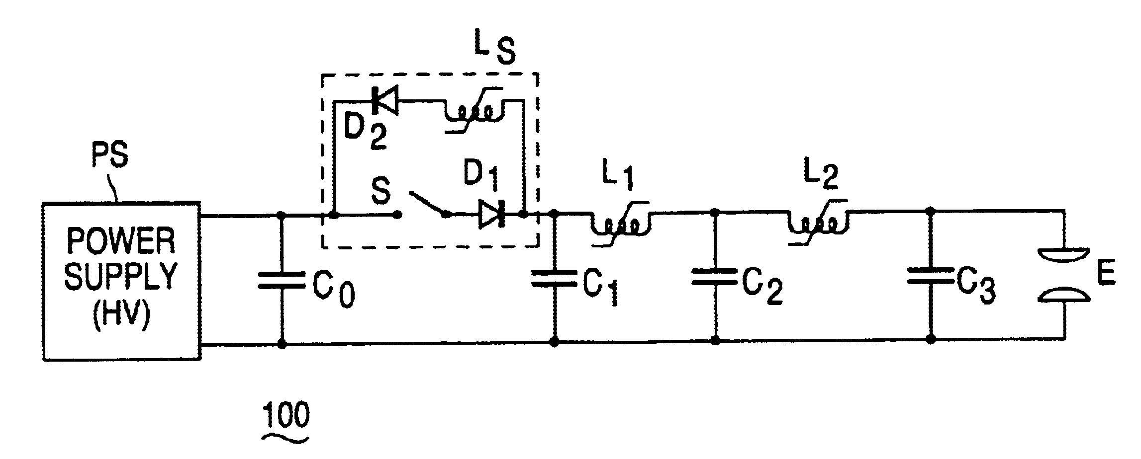
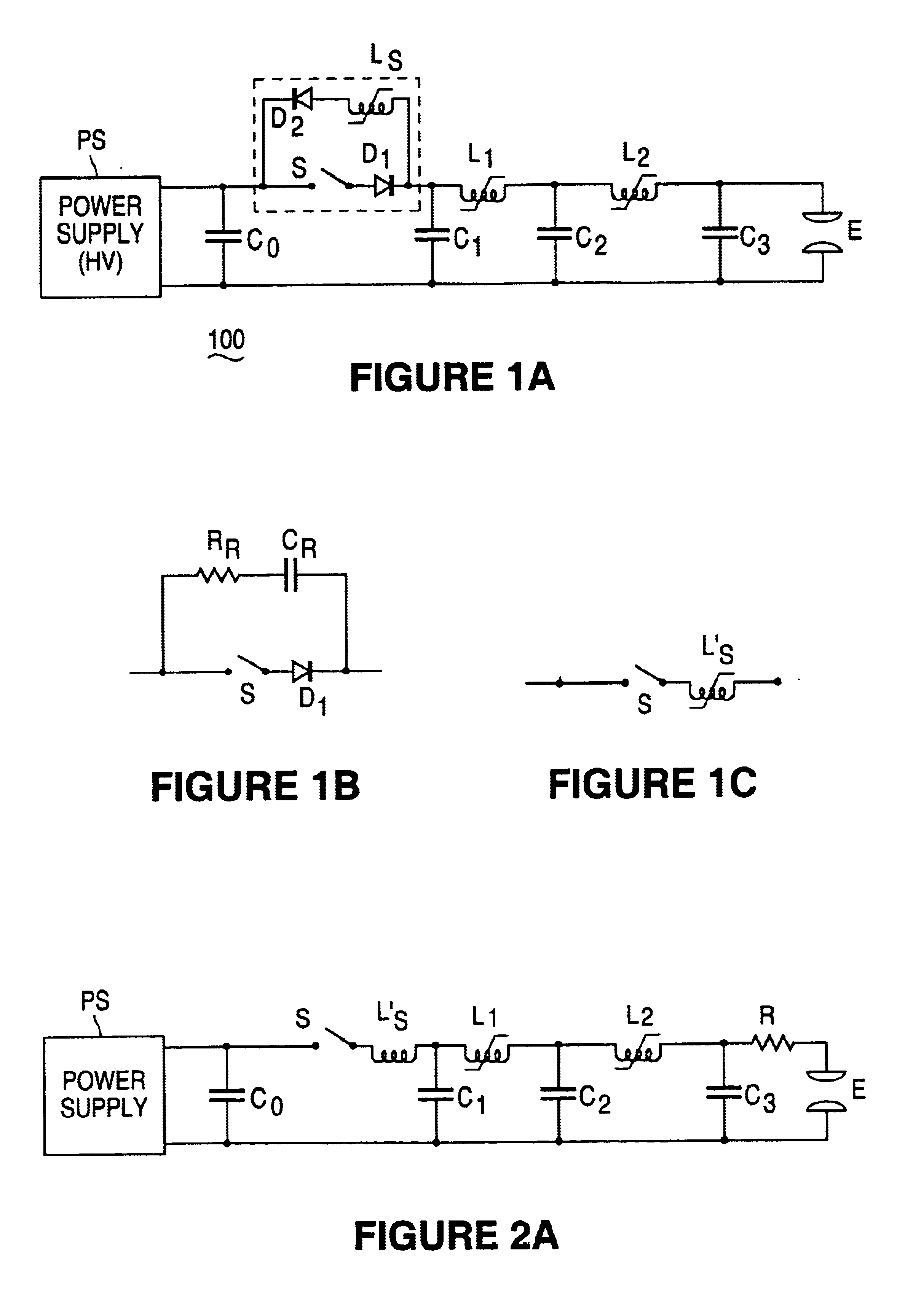
FIG. 1A illustrates a discharge circuit in accordance with a preferred embodiment. It is understood that FIG. 1A is only illustrative of features of the present invention, and other components of a discharge circuit for use with an excimer or molecular fluorine laser system are understood by those skilled in the art (see, e.g., U.S. patent application Ser. No. 6,020,723 and the other references cited and incorporated by reference above). Referring to FIG. 1A, a discharge circuit is shown and is provided with a power supply PS which is configured to provide electrical energy to be stored in primary energy storage capacitor C0. The energy stored in the primary storage capacitor C0 is transferred to a pulse compression circuit through a solid state switch which is described in more detail below. The pulse compression circuit includes a series of transfer loops comprised of capacitor-inductor combinations C1-L1-C2 and C2-L2-C3, which, as stages of pulse compression, are configured to in...


PUM


Abstract

Method and system for providing an excimer or molecular fluorine laser including a laser tube filled with a laser gas surrounded by an optical resonator, where the laser tube has multiple electrodes including a pair of main discharge electrodes connected to a discharge circuit for exciting the laser gas to produce a laser output beam. The discharge circuit has an all solid state switch and preferably does not include a transformer. The solid state switch includes multiple solid state devices that may be capable of switching voltages in excess of 12 kV, such as 14-32 kV or more, or the voltage needed to switch the laser. The series of switches has a rise time of approximately less than 300 ns, and preferably around 100 ns or less. The switch may be capable of switching voltages of slightly more than half, but less than the entire voltage needed to produce laser pulses of desired energies, and a voltage doubling circuit may be used to produce the voltage required to produce the desired output pulse energies. An oscillator-amplifier configuration may be used, wherein an oscillator switch may be capable of switching voltages less than the entire voltage needed to produce the desired laser pulse energies, while the amplifier amplifies the pulses to the desired pulse energies.

Description

BACKGROUND OF THE INVENTION1. Field of the InventionThe present invention relates to a discharge circuit for a pulsed gas laser system such as an excimer or a molecular fluorine laser system. In particular, the present invention relates to a circuit including a solid state switch for providing high voltage, short current pulses to the main laser discharge electrodes of the laser system.2. Description of the Related ArtPulsed gas discharge lasers, emitting in the deep ultraviolet (DUV) and vacuum ultraviolet (VUV) region are widely used in various industrial applications such as microlithography, photoablation, and micro-machining, among others. For microlithographic applications, currently used systems include line narrowed excimer lasers, such as ArF (193 nm) lasers and KrF (248 nm) lasers, as well as molecular fluorine (F2) lasers emitting at 157 nm. It is desired that these lasers be efficient and exhibit high energy stability at high repetition rates, for example, at 1-2 KHz or ...

Claims


Application Information

Patent Timeline
Patent Type & Authority Patents(United States)
IPC IPC(8): H01S3/14H01S3/225H01S3/098H01S3/08H01S3/0975H01S3/097
CPCH01S3/225H01S3/08004H01S3/08009H01S3/0975H01S3/08031
Inventor OSMANOW, RUSTEMSTAMM, UWETARGSDORG, ANDREAS
Owner COHERENT GMBH
Why Eureka
Try Eureka