Method of manufacturing a piezoelectric vibrator unit
a piezoelectric and vibrator technology, applied in the direction of piezoelectric/electrostrictive transducers, generators/motors, conductive pattern formation, etc., can solve the problems of increasing material cost and joule heat generation, so as to reduce the resistance of a common internal electrode, reduce the size of a fixed area, and improve the manufacturing yield
- Summary
- Abstract
- Description
- Claims
- Application Information
AI Technical Summary
Benefits of technology
Problems solved by technology
Method used
Image

Examples
first embodiment
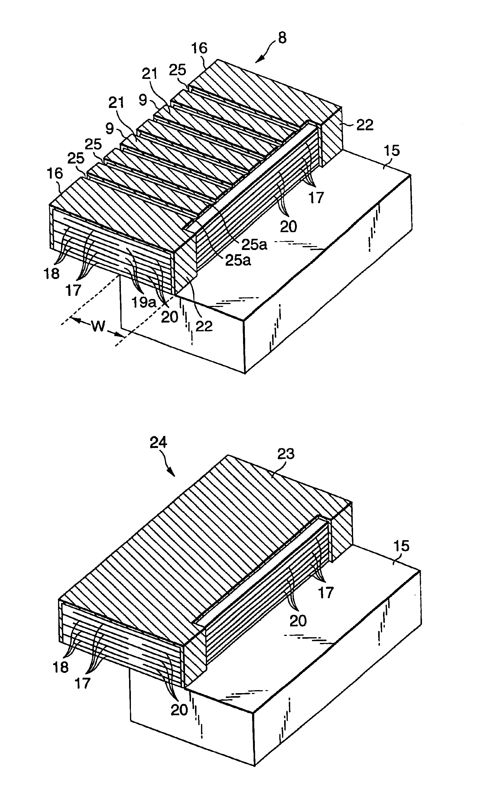
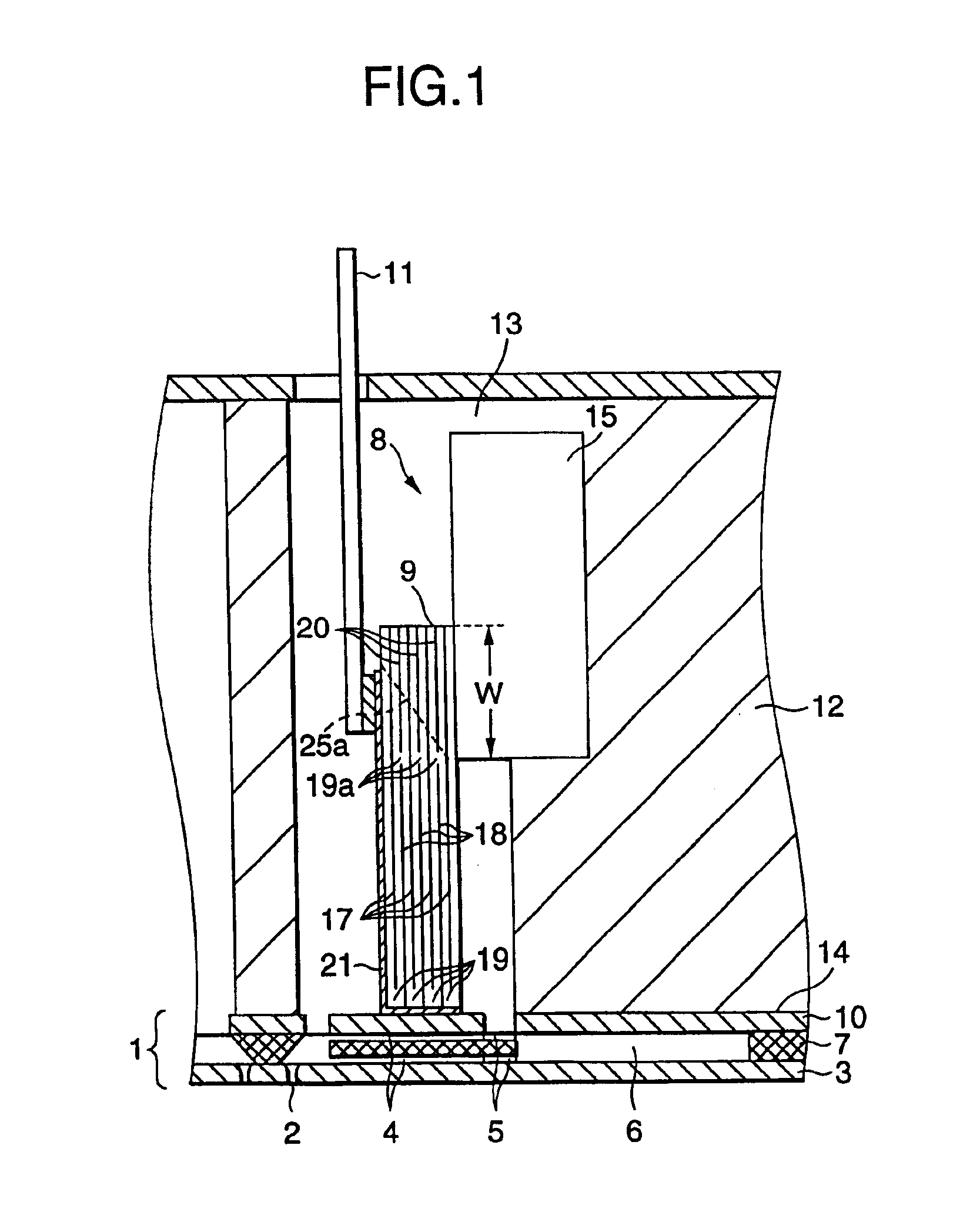
FIG. 1 is a diagram illustrating an ink jet recording head according to the present invention. A channel unit 1 is constituted by integrally laminating a nozzle plate 3, in which nozzle orifices 2 are formed at a constant pitch, pressure generating chambers 4, which communicate with the nozzle orifices 2, a channel forming substrate 7, which includes a reservoir for supplying ink via an ink supply port 5 to the pressure generating chambers 4, and an elastic plate 10, which contacts the distal ends of piezoelectric vibrators 9 of the vertical vibration mode provided in a piezoelectric vibrator unit 8 in order to increase or reduce the volumes of the pressure generating chambers 4.
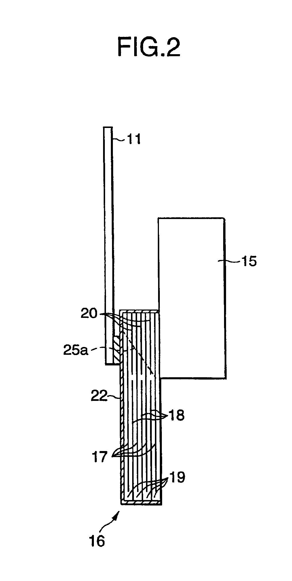
The piezoelectric vibrator unit 8 is stored and fixed to a retainer 13 of a head holder 12, while it is connected to a flexible cable 11 for transmitting an external drive signal, and the channel unit 1 is fixed to an opening face 14 of the holder 12, thereby constituting the recording head.
As is shown in FI...
second embodiment
FIGS. 8A and 8B are diagrams showing the present invention. A piezoelectric vibrator unit 40 is so designed that drive piezoelectric vibrators 41 for ejecting ink droplets are fixed to a fixation base 15 at the pitches at which pressure generating chambers 41 are arranged and that slightly wider dummy piezoelectric vibrators 42 are located at both ends in the direction in which the piezoelectric vibrators 41 are arranged and are fixed to the fixation base 15.
The drive piezoelectric vibrators 41 are so constituted that common internal electrodes 43 and discrete internal electrodes 44 are laminated like sandwiches with piezoelectric material layers 19 in between, and that the common internal electrodes 43 are exposed at the rear face of the fixed end, and the discrete internal electrodes 44 are exposed at the distal end face of the free end.
The piezoelectric material layers 19 are provided to form the same plane as the discrete internal electrodes 44, so that dummy electrodes 45, whic...
PUM
| Property | Measurement | Unit |
|---|---|---|
| Electrical conductor | aaaaa | aaaaa |
| Area | aaaaa | aaaaa |
Abstract
Description
Claims
Application Information
 - R&D
- Intellectual Property
- Life Sciences
- Materials
- Tech Scout
- Unparalleled Data Quality
- Higher Quality Content
- 60% Fewer Hallucinations
Browse by: Latest US Patents, China's latest patents, Technical Efficacy Thesaurus, Application Domain, Technology Topic, Popular Technical Reports.
© 2025 PatSnap. All rights reserved.Legal|Privacy policy|Modern Slavery Act Transparency Statement|Sitemap|About US| Contact US: help@patsnap.com