Automotive alternator stator assembly with rectangular continuous wire

Inactive Publication Date: 2005-03-08
VISTEON GLOBAL TECH INC
View PDF69 Cites 33 Cited by
  • Summary
  • Abstract
  • Description
  • Claims
  • Application Information

AI Technical Summary

Benefits of technology

The automotive alternator stator core assembly in accordance with this invention addresses each of the design and manufacturing goals previously noted. The alternator stator core assembly in accordance with this invention utilizes a unique winding pattern particularly advantageously used with rectangular cross section stator winding conductors. The design

Problems solved by technology

Vehicle audio and telematics systems place further demands on the vehicle's electrical system.
Still further challenges in terms of the output capacity of the motor vehicle's electrical alternators will come with the widespread adoption of electrically assisted power steering and electric vehicle braking systems.
In addition to the challenges of providing high electrical output for the vehicle electrical alternator, further constraints include the desire to minimize the size of the alternator with respect to under hood packaging limitations, and its mass which relates to the vehicle's fuel mileage.
And finally, as is the case with all components for mass-produced motor vehicles, cost remains a factor in the competitive offerings of such components to original equipment manufacturers.
A number of de

Method used


Image

  • Automotive alternator stator assembly with rectangular continuous wire
  • Automotive alternator stator assembly with rectangular continuous wire
  • Automotive alternator stator assembly with rectangular continuous wire

Examples


Embodiment Construction

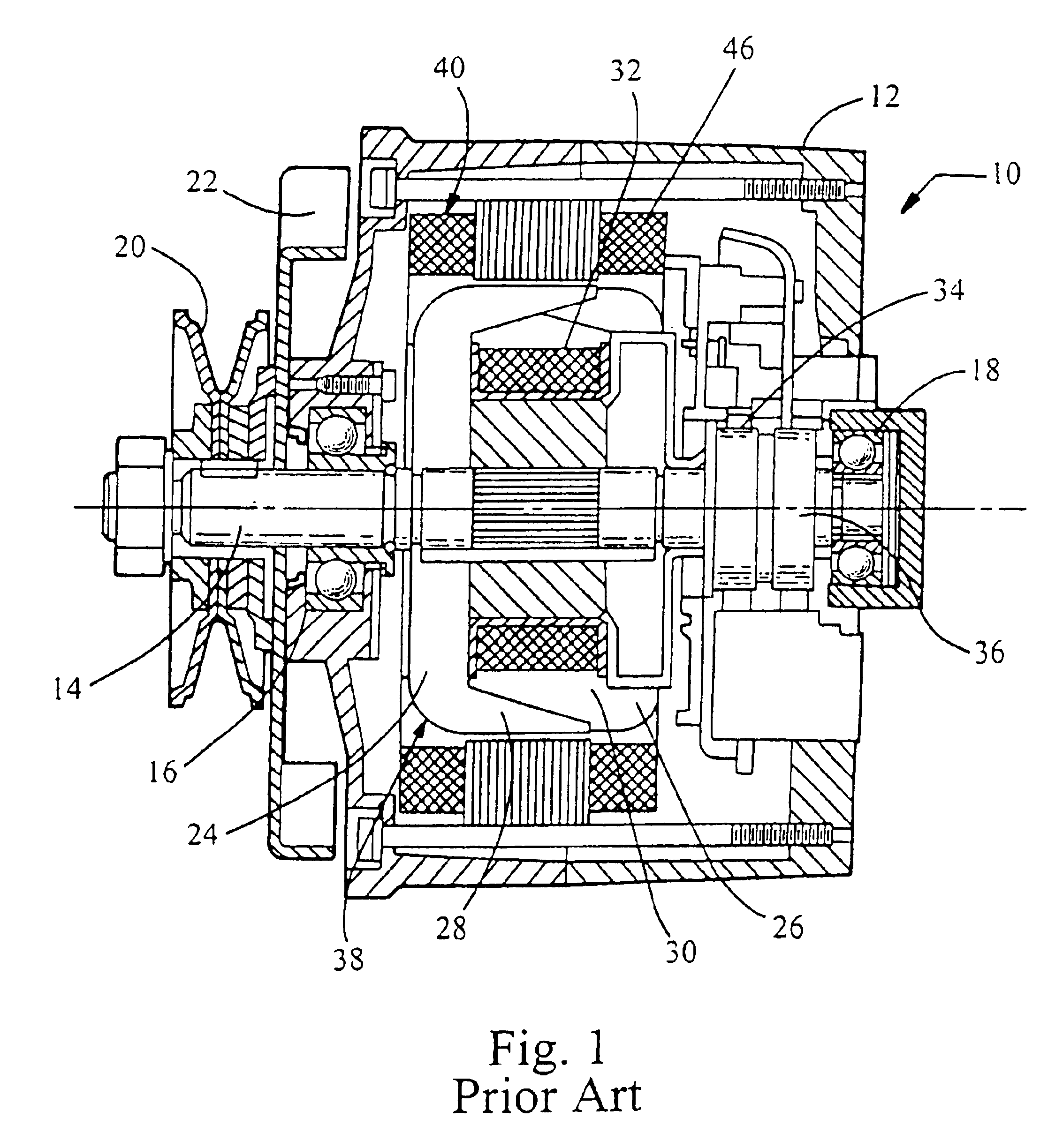
In order to provide a framework for a further detailed description of the preferred embodiments of this invention, FIG. 1 is presented illustrating a prior art electrical alternator configuration. That figure illustrates electrical alternator 10 enclosed with housing 12. Alternator rotor shaft 14 is supported by rolling element bearings 16 and 18. Belt driven pulley 20 is fastened to the protruding front end of rotor shaft 14. Fan 22 rotates with shaft 14 and provides cooling airflow for removing heat from alternator 10. Front and rear alternator poles pieces 24 and 26, respectively, rotate with shaft 14 and have extending claw fingers 28 and 30, respectively. Fingers 28 and 30 interlace to create the well known “claw pole” rotor configuration. Although the “claw pole” rotor is described, one skilled in the art will recognize that the described stator design can be used in conjunction with other types of rotors, such as; permanent magnet non claw pole, permanent magnet claw pole, sa...


PUM

PropertyMeasurementUnit
Temperatureaaaaaaaaaa
Shapeaaaaaaaaaa
Widthaaaaaaaaaa

Abstract

A method of forming a stator core assembly for an electric machine includes: providing two electrical conductors designated as conductor A and conductor B and winding the conductors into the winding slots.

Description

FIELD OF INVENTIONThe invention relates to an automotive electrical alternator, and particularly to an alternator having an improved stator winding configuration.BACKGROUND OF THE INVENTIONThis invention is related to an electrical alternator, of a type particularly adapted for use in motor vehicle applications including passenger cars and light trucks. These devices are typically mechanically driven using a drive belt wrapped on a pulley connected to the crankshaft of the vehicle's internal combustion engine. The belt drives a pulley on the alternator which rotates an internal rotor assembly to generate alternating current (AC) electrical power. This alternating current electrical power is rectified to direct current (DC) and supplied to the motor vehicle's electrical bus and storage battery.While alternators have been in use in motor vehicles for many decades, today's demands on motor vehicle design, cost, and performance have placed increasing emphasis on the design of more effic...

Claims


Application Information

Patent Timeline
IPC IPC(8): H02K3/12H02K3/28
CPCH02K3/12H02K3/28Y10T29/49073Y10T29/49012Y10T29/49071Y10T29/49009
Inventor NEET, KIRK E.
Owner VISTEON GLOBAL TECH INC
Why Eureka
Try Eureka