Method and apparatus for manipulating a sample

a sample and sample technology, applied in the field of scanning probe microscopy, can solve the problems of nudge, present spms do not provide an adequate mechanism for manipulating samples, and can be difficult to manipulate samples,

Inactive Publication Date: 2005-03-08
BRUKER NANO INC
View PDF16 Cites 61 Cited by
  • Summary
  • Abstract
  • Description
  • Claims
  • Application Information

AI Technical Summary

Benefits of technology

Accordingly, the present invention provides for the accurate manipulation of particles, objects, surfaces, and the like on a sample. Also, the present invention can accurately pick up, move, and deposit particles on the sample. In particular, the present invention

Problems solved by technology

Unfortunately, present SPMs do not provide an adequate mechanism for manipulating the sample being imaged.
For example, present SPMs do not adequately provide for accurately picking up, nudging, etc. the sample or portions thereof.
Manipulation of the sample can be difficult because present SPMs do not allow for performing action on what often times are nanoscale objects.
This can create inaccuracies in determining the location of the manipulation probe with respect to an imaging probe because inaccuracies

Method used


Image

  • Method and apparatus for manipulating a sample
  • Method and apparatus for manipulating a sample
  • Method and apparatus for manipulating a sample

Examples


Embodiment Construction

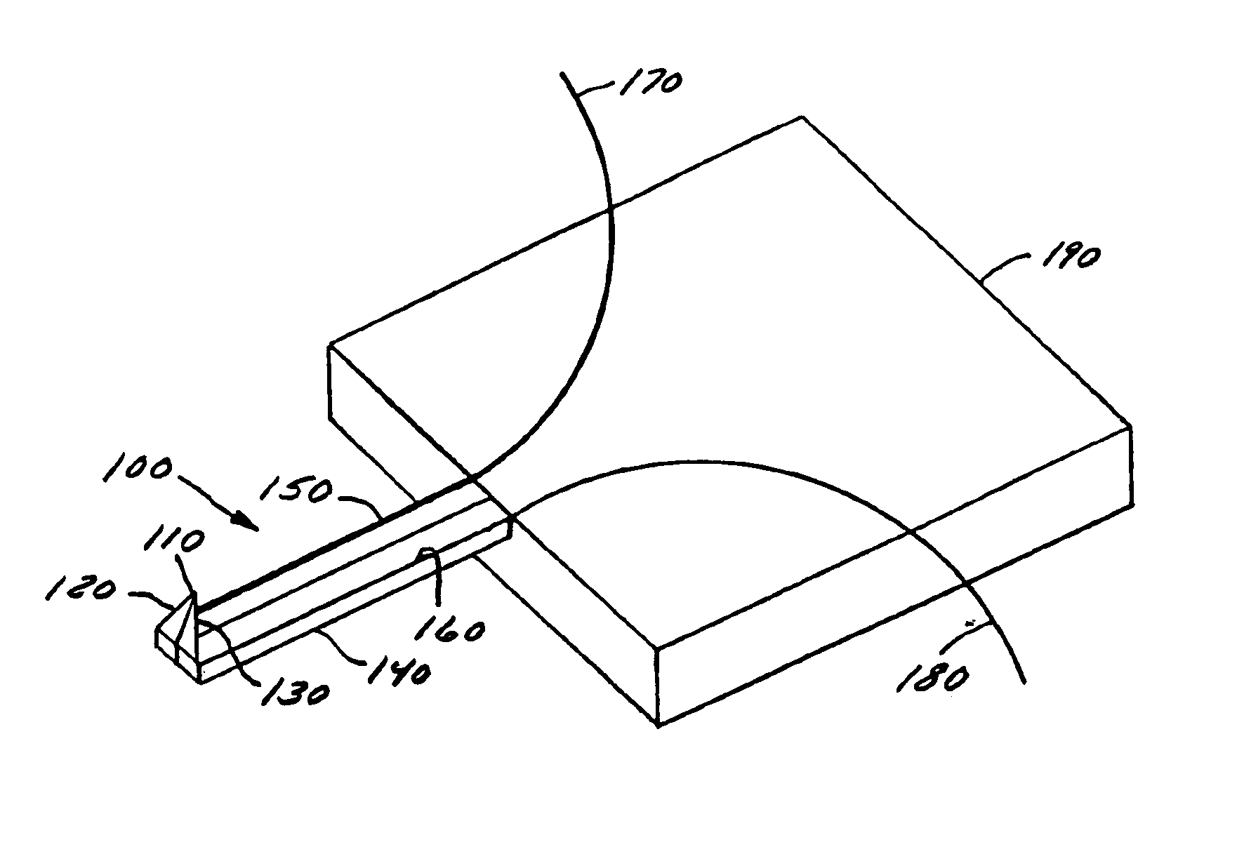
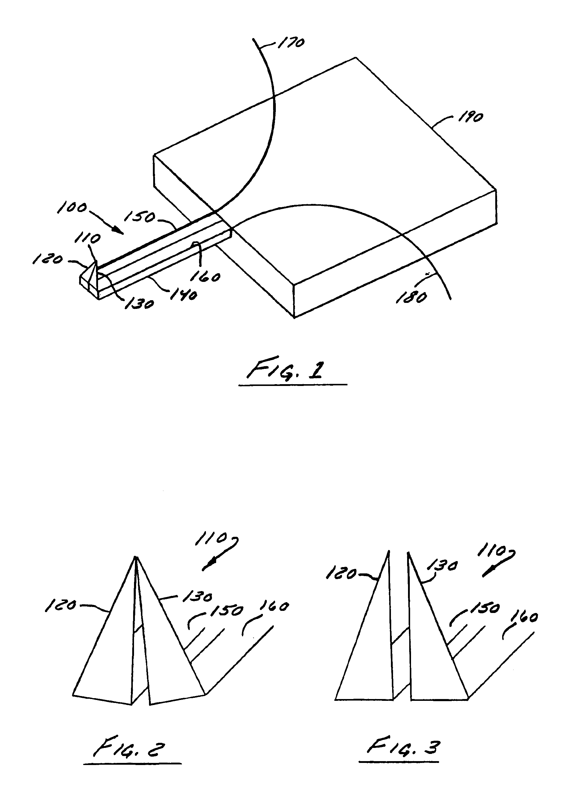
FIG. 1 is an exemplary illustration of a probe 100 particularly adapted for both imaging and manipulating samples, such as biological samples, (e.g., DNA) according to one embodiment. The probe 100 can include a cantilever 140 and a tip or tweezers 110 mounted substantially perpendicular to the cantilever 140. The tip 110 can include a first tip or prong 120 and a second tip or prong 130 mounted substantially perpendicular to the cantilever. The cantilever 140 can be mounted to a base 190 and can have a longitudinal axis running from the end of the cantilever mounted to the base to the opposite, free end of the cantilever. Preferably, the tips 120 and 130 can be mounted substantially perpendicular to the longitudinal axis of the cantilever. The cantilever 140 can include a first cantilever portion 150, and a second cantilever portion 160 disposed generally parallel thereto. A first electrode 170 and a second electrode 180 can be coupled to the tips 120 and 130 or the cantilevers 150...


PUM


Abstract

A method and apparatus for manipulating the surface of a sample including a cantilever, a first tip mounted on the cantilever, and a second tip mounted on the cantilever, the first and the second tip being configured to combine to form an imaging probe and to separate to form a manipulation probe. The first and second tips are configured to form a first position characterized in that the tips combine to form an imaging tip and the first and the second tip are configured to form a second position characterized in that the tips separate to manipulate particles on a surface of a sample. The tips can be configured to form the first position when a voltage is applied across the tips, and preferable extend downwardly from the cantilever substantially perpendicular thereto.

Description

BACKGROUND OF THE INVENTION1. Field of InventionThe present invention is directed to scanning probe microscopy. More particularly, the present invention is directed to a method and apparatus for characterizing and manipulating a sample.2. Description of Related ArtPresently, scanning probe microscopes (SPMs) are typically used to determine the surface characteristics of a sample, commonly biological or semiconductor samples, to a high degree of accuracy, down to the Angstrom scale. An SPM operates by scanning a measuring probe assembly having a sharp stylus over a sample surface while measuring one or more properties of the surface. One example of an SPM is an atomic force microscope (AFM) wherein a measuring probe assembly includes a sharp stylus attached to a flexible cantilever. Commonly, an actuator such as a piezoelectric tube, often referred to as a piezo tube, is used to generate relative motion between the measuring probe and the sample surface. A piezoelectric tube moves in...

Claims


Application Information

Patent Timeline
IPC IPC(8): G01B5/28G01D5/26G12B21/22G12B21/20G12B21/02G12B21/00G01B21/30G01Q10/02G01B11/00G01Q10/04G01Q10/06G01Q30/20G01Q60/00G01Q70/02G01Q70/08G01Q70/16G01Q80/00G01Q90/00
CPCG01B5/28G01D5/26G01Q10/02G01Q10/04B82Y35/00G01Q70/02G01Q70/08G01Q70/16G01Q10/06G01Q80/00
Inventor CHAND, AMIKJOLLER, KEVIN J.BABCOCK, KENNETH L.HARRIS, MICHAEL K.
Owner BRUKER NANO INC
Why Eureka
Try Eureka