Method for determining a lower thread supply, and a sewing machine having a lower thread supply monitoring device

Inactive Publication Date: 2005-03-08
FRITZ GEGAUF AKTIENGES BERNINA NAHMASCHFAB
View PDF3 Cites 17 Cited by
  • Summary
  • Abstract
  • Description
  • Claims
  • Application Information

AI Technical Summary

Benefits of technology

Using a light source situated at a distance radially from the hook body, light beams, directed tangentially to the axis of rotation of the bobbin or of the hook, can be sent through the hook body onto a light-sensitive element, and there the time of the impingement of the first light beam can be compared with the momentary angle of rotation of the hook, and in this way the diameter of the momentary thread supply on the bobbin can be precisely determined. Using the same device, namely the light source and a light-sensitive element that extends over a finite length, the location of the impinging of the light beam can also be compared, together with the knowledge of the momentary angle of rotation of the bobbin, and in this way the diameter of the supply of thread can be determined. Furthermore, using the same system, by measu

Problems solved by technology

For this reason, the monitoring of the momentary lower thread supply and of the pulling off of the lower thread during the sewing process is difficult.
Moreover, the situation is made more diffic

Method used


Image

  • Method for determining a lower thread supply, and a sewing machine having a lower thread supply monitoring device
  • Method for determining a lower thread supply, and a sewing machine having a lower thread supply monitoring device
  • Method for determining a lower thread supply, and a sewing machine having a lower thread supply monitoring device

Examples


example 1 (

Location)

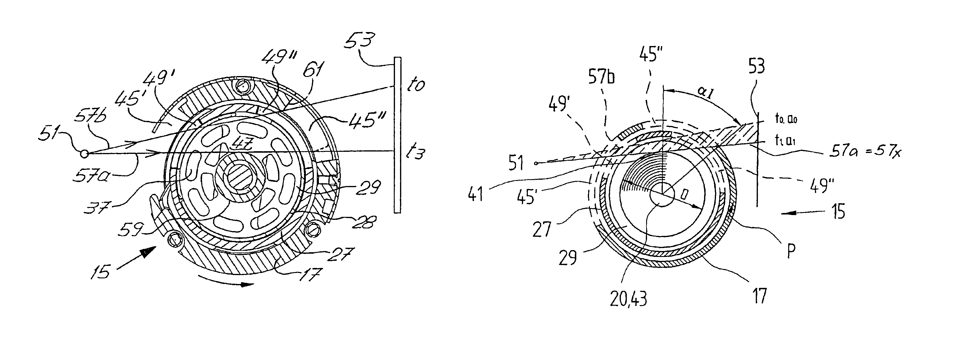
The light receiver 53 recognizes location a1 to a3 of the impingement of the first light beam 57x that impinges on light receiver 53, as soon as the front edge 61 of the opening 45″ permits the light beam 57x to pass through. The recognition of the location (a1 to a3)) of the impingement of the first light beam 57x on the light receiver 53 enables the direct calculation of the packing diameter D, because there is a direct geometrical relation (FIGS. 5a-5c). Alternatively, the location of the last light beam could be acquired before the rear edge 62 on the opening 45″ begins to close the light cone (FIGS. 6a-6c).

example 2 (

time)

The time t1 of the impingement of the light beam 57x is acquired, and is compared with the position of angular rotation alpha of the front edge 61 on hook body 17. From these two parameters, diameter D of the packing can likewise be calculated (FIGS. 5a-5c; FIGS. 6a-6c).

example 3 (

duration of exposure)

The times tx to t0 of the impingement of the first light beam 57a up to the disappearing of the last light beam on the receiver 53, i.e., the duration of exposure, are acquired. Together with the known rotational speed n of the hook 15 and the size of opening 45″, the diameter D of the bobbin packing can likewise be calculated (width of the light cone in FIGS. 6a-6c).


PUM


Abstract

From a light source (51), light beams (57) are directed tangentially through the hook body (17), the hook base (27), and the bobbin case (28), onto a light receiver (53). Using the time (t) or the position of angular rotation of the hook body (17) at the impingement of the first light beam (57), the diameter of the bobbin packing on the lower thread bobbin (29) can be calculated.

Description

BACKGROUNDThe subject matter of the present invention is a method for determining the lower thread supply, and a sewing machine having a lower thread supply monitoring device which includes a light transmitter and a light receiver, in which a light beam bundle from the light transmitter is directed through slits in the hook base and through peripheral openings situated in the hook body, tangential to the bobbin core and to the thread wound thereon, through the packing space between the flanges, and at least one of the light beams is received by the light receiver, and the received signal is forwarded to the machine control unit for the calculation of the bobbin packing diameter.In sewing and embroidery using a sewing machine, it is known that two threads, the upper thread and the lower thread, are looped with one another. The upper thread, called the needle thread, is supplied from a spool situated on or next to the sewing machine; the size of this spool can essentially be freely ch...

Claims


Application Information

Patent Timeline
IPC IPC(8): D05B59/00D05B59/02B65H63/08D05B57/14
CPCB65H63/082D05B59/02D05B57/14B65H2701/31
Inventor FLUCKIGER, HANS
Owner FRITZ GEGAUF AKTIENGES BERNINA NAHMASCHFAB
Why Eureka
Try Eureka