Membrane bioreactor, process and aerator

a bioreactor and membrane technology, applied in the direction of dialysis systems, solid separation, grey water treatment, etc., can solve the problems of high reconstruction cost, low level of treatment achieved, and inability to meet the needs of the user, and achieve the effect of facilitating the flow of mixed liquor

Inactive Publication Date: 2005-03-08
ZENON TECH PARTNESHIP
View PDF102 Cites 96 Cited by
  • Summary
  • Abstract
  • Description
  • Claims
  • Application Information

AI Technical Summary

Benefits of technology

[0010]In other aspects, the invention provides one or more membrane modules located in a membrane tank or zone and an aerator for aerating the one or more membranes or membrane modules at least from time to time. The membrane tank or zone is sealed or substantially sealed such that pressure in the membrane zone or tank increases during at least a portion of a time during which the aerator is operated even though the mixed liquor in the membrane tank or zone becomes less dense. Permeate flow rate increases when pressure in the membrane tank or zone increases. Transmembrane pressure for withdrawing permeate may also be provided by a gravity flow outlet or siphon connected to a permeate side of the one or more membrane modules. The membrane aerator may also be used to generate an air lift effect which facilitates mixed liquor flowing into the membrane tank or zone through an inlet and flowing out of the membrane tank or zone through an outlet. The inlet and outlet may be connected to one or more process tanks or zones.

Problems solved by technology

Increasingly, this method is becoming unacceptable because of the low level of treatment achieved, frequent failures and high cost of reconstruction, contamination of streams and groundwater, and the requirement for large land area to establish septic fields.

Method used


Image

  • Membrane bioreactor, process and aerator
  • Membrane bioreactor, process and aerator
  • Membrane bioreactor, process and aerator

Examples


example 1

[0058]Steady-State Operation at 1.2 m3 / d

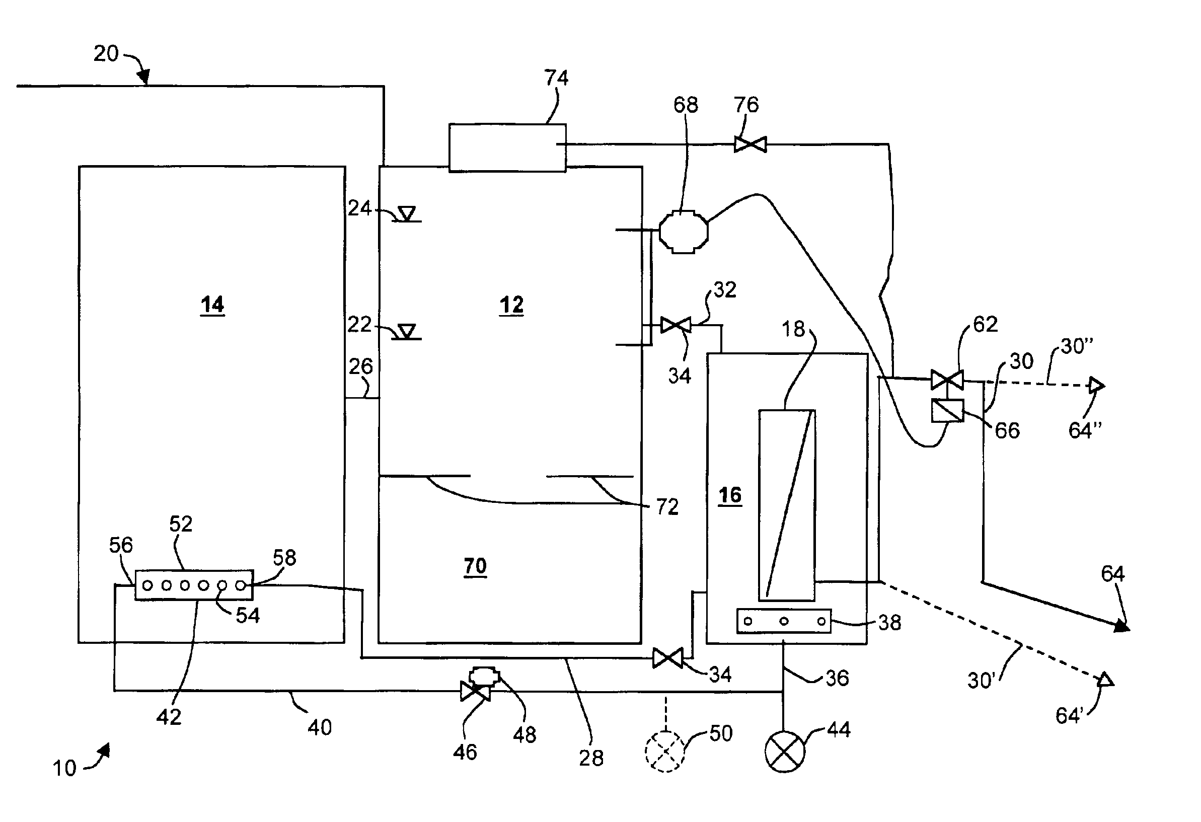
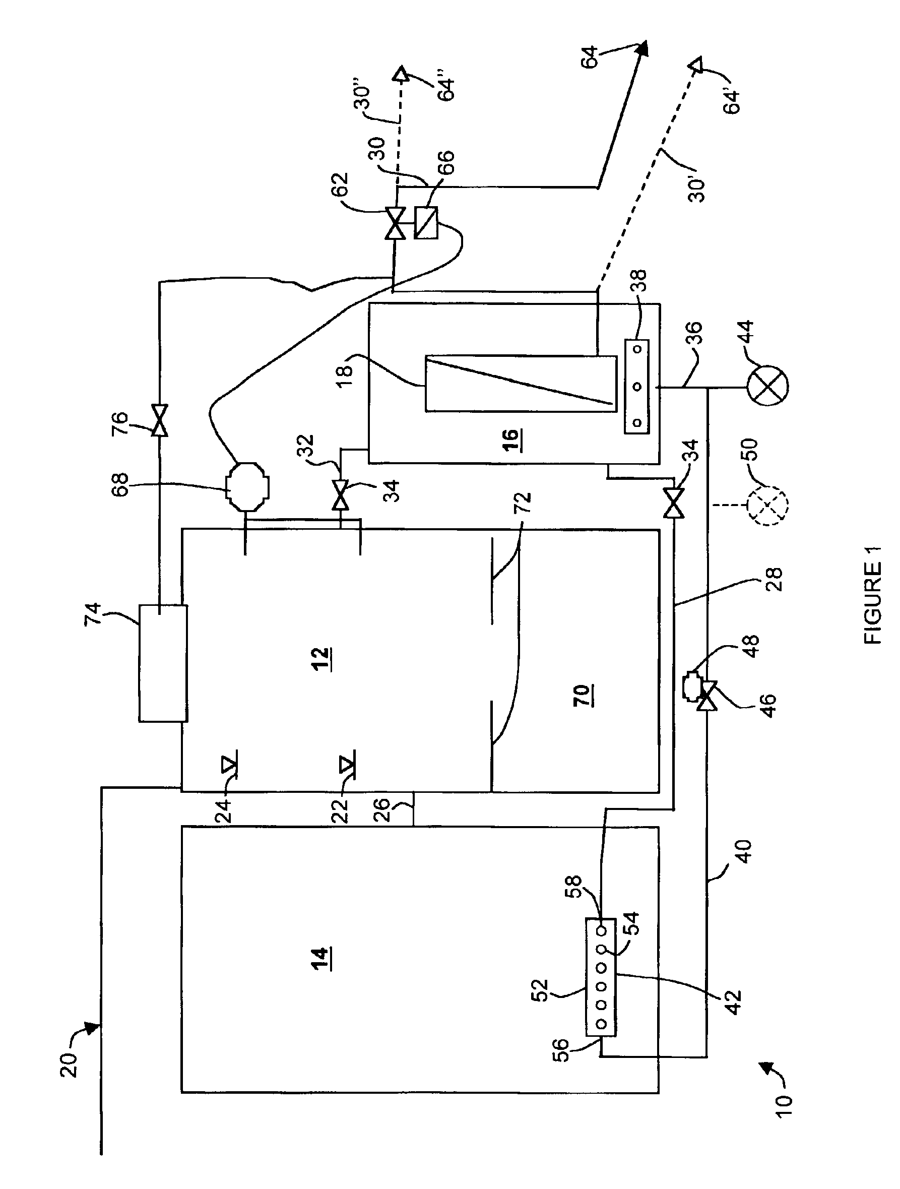
[0059]A pilot system was built and operated as described for the exemplary embodiment. The pilot system was run for two weeks with a steady state feed of 1.2 cubic meters per day of municipal sewage. The pilot system had an anoxic tank and an aerobic tank, each of 800 L volume at depth of 1.8 m in those tanks, and a 200 L membrane tank. The bottom of each of the anoxic tank and aerobic tank were 0.5 meters above the bottom of the membrane tank. The system was operated at a generally constant mixed liquor depth of about 1.5 meters above the bottom of the membrane tank. At this depth, the system had a total liquid volume of about 1080 L. Flow rate in the membrane air line was 8.5 cubic meters at standard conditions per hour when air flows to the membranes. A single blower provided a continuous air flow and the entire air flow was switched between the aerobic tank and membrane tank every 7 seconds so that the rate of air flow in each of the aerob...

example 2

[0063]Development of Pressure in the Membrane Tank and Its Effect on Permeation During Membrane Aeration Cycle

[0064]The system described in example 1 was used for a membrane tank pressurization test. A pressure sensor was installed onto the bottom of the membrane tank 16. The sensor read 15.3 kPag when the membrane air was on and 11.9 kPag when the membrane air was off. The permeate flow rate when the air was on was 127 L / h, and 86.3 L / h when the air was off.

example 3

[0065]Demonstration of Recycle of Mixed Liquor from Aerobic to Anoxic Tank through Membrane Tank

[0066]For a period of about 10 days during the test of example 1, the recycle flow rates were measured and average values calculated. With the mixed liquid level in the anoxic tank 12 set at 1.5 meters above the bottom of the membrane tank, recycle of mixed liquor from the aerobic tank to the anoxic tank via the membrane tank was visually confirmed. A magnetic flow meter installed on the aerobic line 28 recorded an average flow rate of 0.44 m3 / h, at a total air flow rate of 8.5 m3 / h. This recirculation flow rate was 8.8 times the average permeate flow rate.


PUM

PropertyMeasurementUnit
time periodaaaaaaaaaa

Abstract

A reactor has an aerobic tank, an anoxic tank and a sealed membrane tank with conduits for circulating mixed liquor between them. Permeation starts when the mixed liquor reaches a high level and stops when the mixed liquor reaches a low level. A sensor, for detecting the mixed liquor level, may stop and start permeation. Pressure builds in the membrane tank when membrane air is on. Transmembrane pressure is also provided by gravity flow or siphon. Membrane air generates an air lift which drives the mixed liquor circulation. The total amount of air provided by an air source is divided and varied in time between the membrane aerator and the process aerator. The process aerator acts as a screening inlet to the conduit to the membrane tank. Chemical maintenance cleaning is provided by gravity flow.

Description

FIELD OF THE INVENTION[0002]This invention relates to a wastewater treatment process or apparatus, to a membrane bioreactor, to an aerator and to a method and system for treating home, multi-residential, commercial, institutional or industrial wastewater such as black or gray water.BACKGROUND OF THE INVENTION[0003]Currently, many small wastewater treatment systems use a septic tank, followed by a septic field for final purification and discharge. Increasingly, this method is becoming unacceptable because of the low level of treatment achieved, frequent failures and high cost of reconstruction, contamination of streams and groundwater, and the requirement for large land area to establish septic fields.[0004]Japanese publication 2000-028675, German application DE 198 07 890 A1 and PCT publication No. WO 00 / 37369 describe wastewater treatment systems using membranes.[0005]PCT Publication No. WO 00 / 21890 describes a cyclic aeration system.[0006]Japanese publication JP 2002-066261 descri...

Claims


Application Information

Patent Timeline
Patent Type & Authority Patents(United States)
IPC IPC(8): C02F3/12C02F3/30
CPCC02F3/1215C02F3/1273C02F3/302B01D61/22B01D65/02B01D65/08C02F3/1268Y10S210/903C02F2103/002C02F2103/005C02F2209/42B01D2311/2642B01D2313/26B01D2315/06B01D2321/04B01D2321/16B01D2321/185B01D2321/40Y02W10/10
Inventor LIU, MINGGANGHUSAIN, HIDAYATCOTE, PIERREPOTTINGER, IAN
Owner ZENON TECH PARTNESHIP
Why Eureka
Try Eureka