Silicon nitride member, method for manufacturing the same, and cutting tool

Inactive Publication Date: 2005-03-08
NGK SPARK PLUG CO LTD
View PDF30 Cites 5 Cited by
  • Summary
  • Abstract
  • Description
  • Claims
  • Application Information

AI Technical Summary

Benefits of technology

The present invention has been achieved in view of the above problems, and an object of the present invention is to provide a silicon nitride member exhibiting little impairment in strength even when a

Problems solved by technology

A tensile stress remaining in the substrate surface is the primary cause for impairment in the strength of the substrate of a silicon nitride

Method used


Image

  • Silicon nitride member, method for manufacturing the same, and cutting tool
  • Silicon nitride member, method for manufacturing the same, and cutting tool
  • Silicon nitride member, method for manufacturing the same, and cutting tool

Examples


Example

First, samples of Example Nos. 3, 4, 6, 9, and 12 to 14, which fall within the scope of the present invention, were manufactured by the method described previously in the Embodiments section.

The samples assumed the form of a test piece for use in the 3-point bending test prescribed in JIS R1601 (1981) and were manufactured under the heat treatment conditions (conditions of primary sintering) shown below in Table 1. Twenty samples were manufactured for each of the Examples. Of the 20 samples, 10 samples were not coated with a hard film, and 10 other samples were coated with a hard film. Also, for use in a wear resistance test, 10 cutting tool samples were manufactured for each of the Examples by the method described previously in the Embodiments section.

Example

Samples of Comparative Example Nos. 1, 2, 5, 7, 8, 10, 11, and 15 to 17, which fall outside the scope of the present invention, were manufactured.

The samples assumed the form of a test piece for use in the bending test and were manufactured under the heat treatment conditions (conditions of primary sintering) shown below in Table 1. Twenty samples were manufactured for each of the Comparative Examples. Of the 20 samples, 10 samples were not coated with a hard film, and 10 other samples were coated with a hard film. Also, for use in a wear resistance test, 10 cutting tool samples were manufactured for each of the Comparative Examples.

(1) When the samples of the Examples and the Comparative Examples were manufactured, the samples were measured for a change in weight (volatilization rate) associated with primary sintering. The average of measured values was calculated for each of the Examples and the Comparative Examples. The results are shown in Table 2.

(2) Ten samples of each of the ...

Example

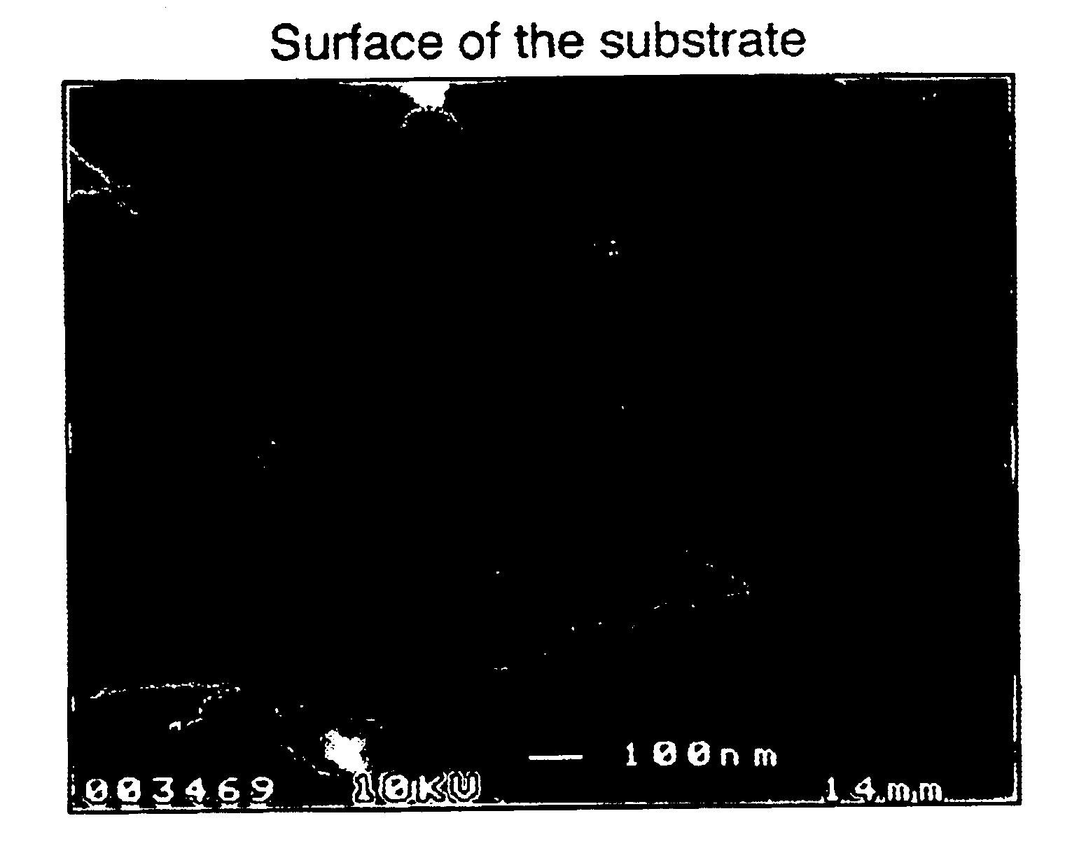
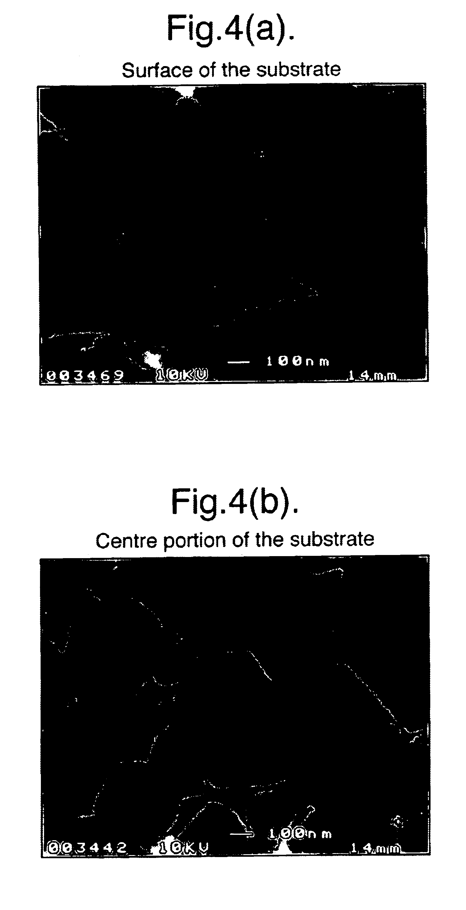
c) As seen from Tables 1 and 2, the samples of Example Nos. 3, 4, 6, 9 and 12 to 14, which fall within the scope of the present invention, exhibited a volatilization of 1.5% to 3.5% by weight and an amount of grain boundary phase of 50% to 70% by volume as measured at the substrate surface.

As a result, the samples of the Examples exhibited a strength ratio not less than 70, indicating a low impairment in strength after coating with the hard film. The samples also exhibited a small amount of flank wear not greater than 0.2 mm and a small amount of notch wear not greater than 0.22 mm. Thus, the cutting tools of the Examples have excellent resistance to chipping and wear resistance and are thus favorably applicable not only to normal cutting but also, for example, to heavy cutting.

By contrast, the samples of Comparative Example Nos. 1, 2, 5, 8, 11 and 15 respectively exhibited a volatilization rate of 1, 1.1, 1.3, 1.3, 1.3 and 1.3% by weight and an amount of grain boundary phase of 90%...


PUM

PropertyMeasurementUnit
Temperatureaaaaaaaaaa

Abstract

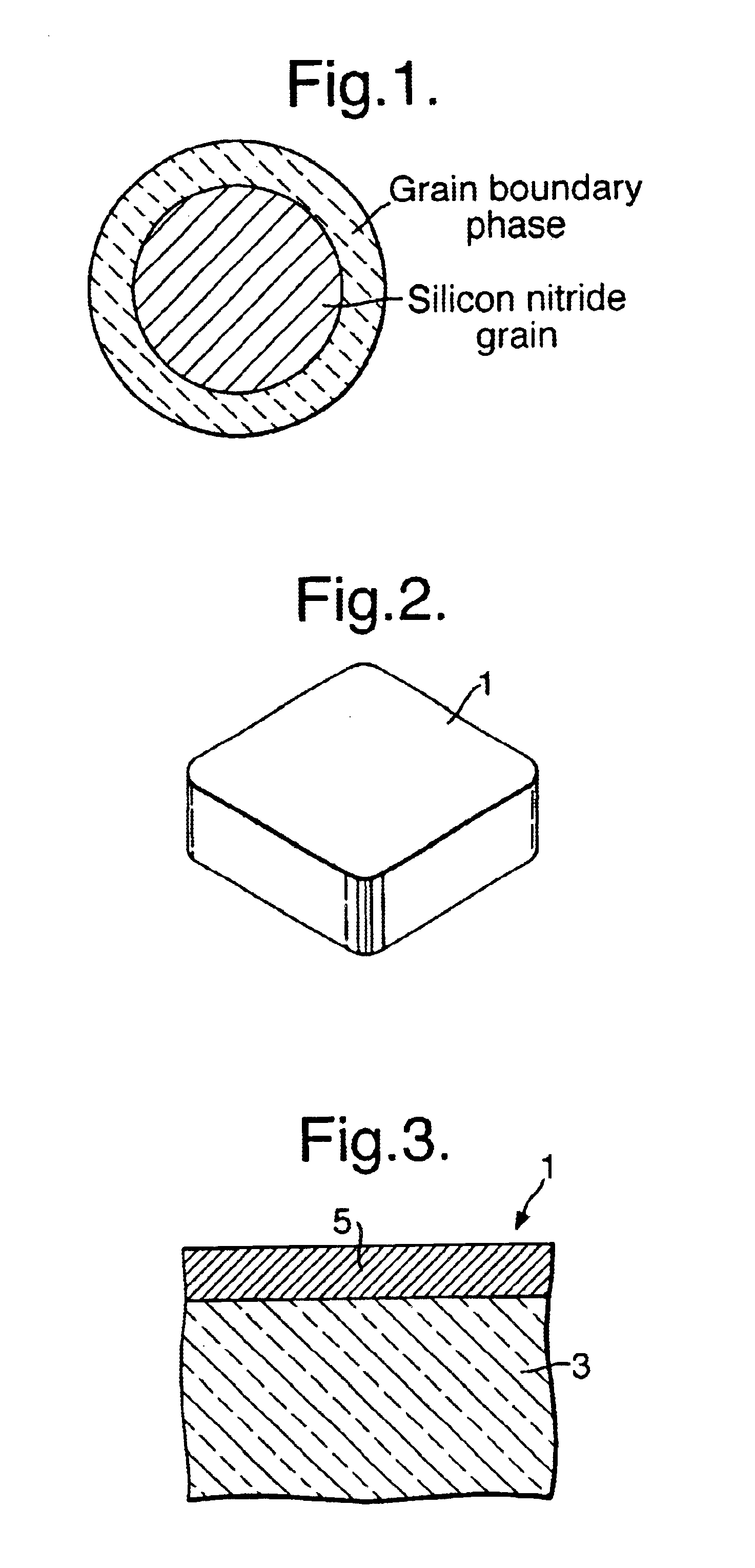
A silicon nitride member, a method for manufacturing the silicon nitride member and a cutting tool are disclosed. A cutting tool 1 includes a substrate 3 formed through sintering of a silicon nitride material, and a hard film 5 composed of a plurality of hard-component layers. The cutting tool 1 is characterized in that: when the amount of a grain boundary phase as measured at a central portion (for example, the barycenter) of the substrate 3 is taken as 100% by volume, the amount of the grain boundary phase at a depth of 300 μm from the surface of the substrate 3 is 50% to 70% by volume; when the strength of the substrate 3 as measured before coating with the hard film 5 is taken as 100%, the hardness as measured after coating with the hard film 5 is 70% to 95%; and a change in weight of the substrate 3 associated with sintering is 1.5% to 3.5% by weight.

Description

BACKGROUND OF THE INVENTION1. Field of the InventionThe present invention relates to a silicon nitride member including a substrate formed through sintering of a silicon nitride material, and a hard film formed on the surface of the substrate, as well as to a method for manufacturing the same and to a cutting tool.2. Description of the Related ArtConventionally, in order to enhance wear resistance of a sintered member, such as a ceramic member, the surface of a substrate of, for example, a sintered silicon nitride member is coated with a hard film composed of hard components, such as TiCN.Examples of the above-mentioned coating method include a CVD (chemical vapor deposition) process and a PVD (physical vapor deposition) process, in which hard components are deposited on the substrate surface to thereby form a hard film on the same.When a sintered member coated with a hard film was used as, for example, a cutting tool, the cutting tool (a coated tool) exhibited significantly enhance...

Claims


Application Information

Patent Timeline
IPC IPC(8): C04B41/45C04B41/52C04B41/89B23B27/14B23P15/28C04B35/584C04B35/593C04B41/87
CPCC04B41/009C04B41/89C04B41/52C04B41/4531C04B41/5061C04B41/5068C04B41/5031C04B41/524C04B35/584Y10T428/24942Y10T428/31C04B35/5935C04B2235/3206C04B2235/3217C04B2235/3224C04B2235/3878C04B2235/5445C04B2235/6567C04B2235/6581C04B2235/662C04B2235/75C04B2235/85C04B2235/96
Inventor ABUKAWA, KOHEI
Owner NGK SPARK PLUG CO LTD
Why Eureka
Try Eureka