Photo detector methods to reduce the disabling effects of displacement current in opto-couplers

a technology of displacement current and photo detector, which is applied in the direction of material analysis, instruments, radio frequency controlled devices, etc., can solve the problems of affecting the normal communication process of the opto-coupler, data extraction is difficult, and errors are easy to be mad

Inactive Publication Date: 2005-03-08
WORLEY EUGENE ROBERT
View PDF2 Cites 6 Cited by
  • Summary
  • Abstract
  • Description
  • Claims
  • Application Information

AI Technical Summary

Benefits of technology

According to the present invention, there is provided a means by which the displacement current flowing between two electrically isolated but optically linked semiconductor devices will not cause disruption in the optical communication process between the two semiconductor devices. These methods include using two detectors for differential sensing, using a ...

Problems solved by technology

Unfortunately, a displacement current can flow from the LED side of the opto coupler into the photo detector and cause an electrical output from the photo detector in addition to the electrical output produced by the light.
The displacement current is a consequence of the unavoidable capacitance coupling between the LED side of the opto-coupler and the photo detecto...

Method used


Image

  • Photo detector methods to reduce the disabling effects of displacement current in opto-couplers
  • Photo detector methods to reduce the disabling effects of displacement current in opto-couplers
  • Photo detector methods to reduce the disabling effects of displacement current in opto-couplers

Examples


Embodiment Construction

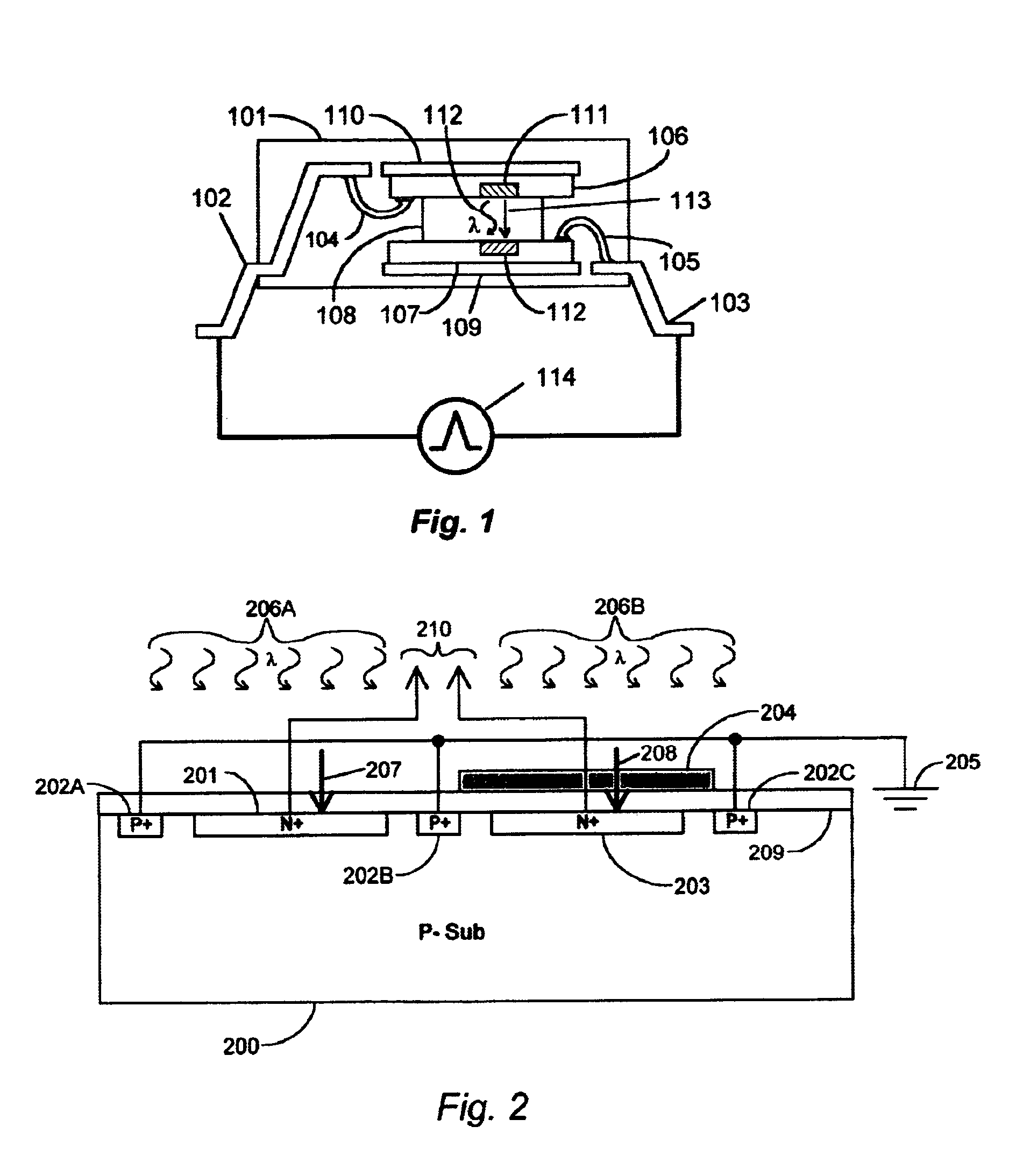
FIG. 2 shows an example of a differential light detector which can be used to null out a displacement current induced by the light source elements. Placed in a P type silicon substrate 200 is an N+ implant or diffusion 201, a second N+ implant 203, and three P+ implants, 202A, 202B, and 202C. The first N+ implant 201 forms an N+ / P junction diode and the second N+ implant 203 forms a second N+ / P junction diode. P+ implants 202A, 202B and 202C form substrate ties or a means of connecting metal conductors to the P substrate 200. Thus, the P substrate 200 areas near the N+ junctions 201 and 203 are robustly tied to ground 205 via the P+ ties 202A, 202B, and 202C.

The diode junction formed with the N+ implant 201 is used as a photo detector in this example. Light 206A coming from the LED source passes through a transparent dielectric 209 such as SiO2 and into the diode formed by the N+ implant 201 thereby creating a photo current. The second diode formed with the N+ implant 203 is identic...


PUM


Abstract

This invention discloses the several means by which transient noise due to capacitance related displacement current can be excluded from the optical signal coming from a silicon detector used in opto-couplers. The exclusion of such noise permits a high degree of detector sensitivity which permits the use of low efficiency silicon based LEDs for opto-coupler applications.

Description

BACKGROUND OF THE INVENTION1. Field of the InventionThis invention relates to the field of semiconductor photo detectors used in opto-couplers, and particularly to reducing the disabling effect of displacement current in photo diodes used in opto couplers.2. Description of the Related ArtOpto couplers are used to allow two electrical systems to communicate with each other while remaining electrically isolated. This communication is achieved by sending light signals using an electrically activated light emitter, typically a Light Emitting Diode (LED), to a photo detector which converts the light signals back into electrical signals. The light passes through a transparent insulator thereby electrically isolating the light emitter and its associated circuitry from the light detector and its associated circuitry. The associated circuitry of the LED side of the optocoupler can include an LED driver, amplifier, etc. The associated detector circuitry can include an amplifier, output driver...

Claims


Application Information

Patent Timeline
IPC IPC(8): H01L31/173H01L31/16
CPCH01L31/173H01L31/162
Inventor WORLEY, EUGENE ROBERT
Owner WORLEY EUGENE ROBERT
Why Eureka
Try Eureka