Hybrid vehicle power control apparatus and hybrid construction equipment using the power control apparatus

a technology of hybrid construction equipment and power control apparatus, which is applied in the direction of propulsion using engine-driven generators, propulsion parts, gas pressure propulsion mounting, etc., can solve the problems of lowering fuel efficiency, lowering charging/discharging efficiency, and deteriorating performance of storage devices

Inactive Publication Date: 2005-03-08
KOBELCO CONSTR MASCH CO LTD +1
View PDF21 Cites 57 Cited by
  • Summary
  • Abstract
  • Description
  • Claims
  • Application Information

AI Technical Summary

Benefits of technology

In the above arrangement, the first controller is allowed to send an electrical command signal, e.g., a current command value, which enables to maintain the voltage of the DC line at a substantially constant level, to the first power converter, which in turn outputs the DC power corresponding to the inputted electrical command signal, and the second controller is allowed to send an electrical command signal, e.g., a current command value, which enables to maintain the voltage of the DC line at a substantially constant level, to the second power converter, which in turn outputs the DC power corresponding to the inputted electrical command signal. This arrangement secures power supply from the generator or from the storage device just enough for the demanded power from the motor.

Problems solved by technology

This arrangement can obviate drawbacks such as lowering of fuel efficiency due to increase of a burden to the engine for driving the generator beyond a predetermined level, and forcible suspension of driving of the engine due to overload of the engine.
This arrangement can obviate drawbacks such as lowering of charging / discharging efficiency due to increase of the charging / discharging currents of the storage device beyond the predetermined values, respectively, deterioration of performance of the storage device, and shortening of the useful life of the storage device.

Method used


Image

  • Hybrid vehicle power control apparatus and hybrid construction equipment using the power control apparatus
  • Hybrid vehicle power control apparatus and hybrid construction equipment using the power control apparatus
  • Hybrid vehicle power control apparatus and hybrid construction equipment using the power control apparatus

Examples


first embodiment

(a) First Embodiment

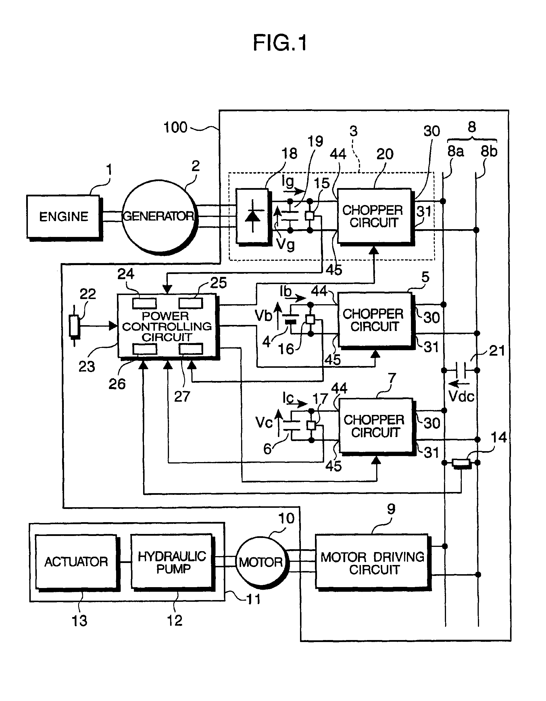
A power control apparatus in accordance with the first embodiment of the invention is comprised of, as shown in FIG. 1, an engine 1, an alternate-current (AC) generator 2, an electric motor 10, a load 11, and an electric circuit section 100.

The engine 1 is directly connected with the AC generator 2. The AC generator 2 outputs three-phase AC power by being driven by the engine 1.

The motor 10 may be an induction motor, a direct-current (DC) motor, a synchronous motor, or its equivalent.

The load 11 includes a hydraulic pump 12 and an actuator 13. The hydraulic pump 12 is drivingly rotated by the motor 10. The actuator 13 includes a hydraulic cylinder which is operated by pressure oil fed from, e.g. the hydraulic pump 12. The actuator 13 is used to drive a working attachment such as a boom and an arm.

The electric circuit section 100 is configured in such a manner that a circuit 3 for converting power of the generator 2 (a generator power converting circuit 3) has an ...

second embodiment

(b) Second Embodiment

Now, a power control apparatus for use in a hybrid vehicle in accordance with a second embodiment of the invention is described. The electrical configuration of the second embodiment is identical to that of the first embodiment shown in FIGS. 1 and 2 except that the second embodiment is different from the first embodiment in control procedure of the CPU 27 (see FIG. 1) of the power control circuit 23.

FIGS. 5 and 6 are flowcharts of the control procedure of a CPU 27 of a power control circuit 23 in the second embodiment.

Referring to FIG. 5, steps ST30 through ST32 are identical to steps ST1 through ST3 in FIG. 3, and accordingly, description thereof is omitted herein.

In ST33, a capacitor current command value Ic*, which is a command value of a capacitor current Ic flowing in a chopper circuit 7, is calculated by using a capacitor voltage Vc received in ST31 and a power command value Pw* calculated in ST32 by implementing the equation (13):

Ic*=Pw* / Vc  (13)

Subseque...

third embodiment

(c) Third Embodiment

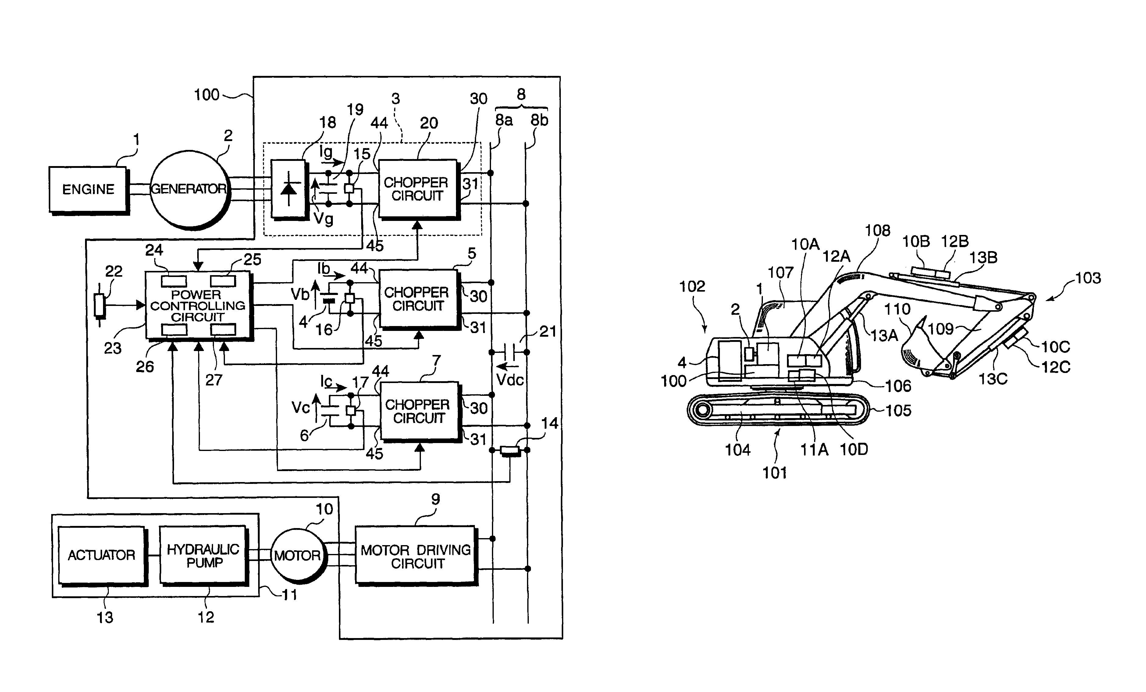
Next, an embodiment of a hybrid construction machine according to this invention is described as a third embodiment of the invention. FIG. 7 is a diagram showing an entire construction of a hybrid hydraulic excavator as the third embodiment. It should be noted that elements of the third embodiment identical to those of the first embodiment are denoted at the same reference numerals.

The hydraulic excavator is comprised of, as shown in FIG. 7, a lower traveling body 101, an upper rotating body 102, and an excavation attachment 103 which is mounted on a front part of the upper rotating body 102. The hydraulic excavator further comprises a power control apparatus in accordance with the first embodiment of the invention.

The lower traveling body 101 includes a right-side crawler frame 104 and a left-side crawler frame 105 provided laterally at the opposite sides thereof (in FIG. 7, only one of the crawler frames is illustrated). The crawler frames 105 (sic) are individ...


PUM


Abstract

An object of the invention is to maintain high vehicle driving performance and system efficiency by preventing reductions in the traction characteristic and the maximum driving speed of a vehicle.
The invention relates to an electrical system for an electric automotive vehicle for driving the vehicle by supplying an electric power of a direct-current power supply to an electric motor for driving wheels via a semiconductor power converter for driving the wheels such as an inverter and speed-variably driving this electric motor or an electrical system for an electric automotive vehicle using an engine and a direct-current power supply as driving sources. A booster chopper 200 is connected between a battery device 1 or 4 as the direct-current power supply and an inverter 2 or a semiconductor power converter 100, and is controlled so that a direct-current input voltage of the inverter 2 or the like becomes substantially constant.

Description

TECHNICAL FIELDThis invention relates to a power control apparatus for use in a hybrid vehicle loaded with an engine and an electric motor, and a hybrid construction machine loaded with such a power control apparatus.BACKGROUND ARTHeretofore, there have been proposed a variety of hybrid vehicles each of which is mounted with an engine and an electric motor and which is so constructed as to drive a load by the motor, and some of these hybrid vehicles are in practical use.For instance, there is proposed a hybrid vehicle in which a battery is charged with electric power generated from a generator by driving of an engine, and the electric motor is selectively driven either by electric power from the battery or electric power from the generator.In the above-constructed hybrid vehicle, it is desirable to optimally control power distribution between the battery and the generator depending on electric power demanded from a load by way of the motor, considering various requirements such as s...

Claims


Application Information

Patent Timeline
Patent Type & Authority Patents(United States)
IPC IPC(8): B60L11/12B60L15/04B60L11/02B60K6/04B60L15/00B60K6/00E02F9/20H02J7/14H02J7/34H02J1/10B60K6/20B60K6/28B60K6/46B60L11/18B60L50/15B60W10/08B60W10/26B60W20/00H02J1/00H02J7/00
CPCB60K6/34B60L11/12B60L11/123B60L11/1853B60L15/04B60W10/08E02F9/2025H02J1/10H02J7/1492H02J7/34B60K6/46Y02T10/7241B60L2200/40B60L2210/20B60L2210/40B60W20/00B60W2300/17B60W2510/244B60Y2200/41Y02T10/6217Y02T10/645Y02T10/7005Y02T10/7022Y02T10/705Y02T10/7077Y02T10/725Y02T10/92B60L50/15B60L50/61B60L58/18E02F9/2075E02F9/2091Y02T10/62Y02T10/64Y02T10/70Y02T10/7072Y02T10/72B60K6/28B60W10/24
Inventor KOMIYAMA, MASAYUKISORA, TOSHIOKOYAMA, MASATOKATAOKA, MICHIO
Owner KOBELCO CONSTR MASCH CO LTD
Why Eureka
Try Eureka