System and method for combining multiple satellite channels into a virtual composite channel

Inactive Publication Date: 2005-03-08
VIRLITE COMM LIMITED LIABILITY
View PDF8 Cites 9 Cited by
  • Summary
  • Abstract
  • Description
  • Claims
  • Application Information

AI Technical Summary

Benefits of technology

The timing signal if required for synchronization can be added to the virtual satellite channel using one of two exemplary methods, but the instant invention is not so limited. A first exemplary method requires that a narrow bandwidth signal be transmitted across each satellite in the virtual channel. The narrow band signal requires a small allocation of the available spectrum, but provides a dedicated timing signal on each satellite actively carrying virtual satellite channels. The narrow band timing signal provides propagation delay information to virtual channel receiving terminals having one or more subchannels on the satellite. The timing signal could consist of one or more of the following exemplary signals, but the instant invention is not so limited. A first exemplary signal is a carrier modulated digitally by a binary pseudorandom noise sequence. A second exemplary signal is a periodic pulse. The pulse could be time-dispersed prior to transmission to create a signal with improved peak to average waveform properties. The receiving terminal in this example would reverse the time-dispersal process to recover a narrow-time pulse. The time period of either exemplary signal above described, after whi

Problems solved by technology

Those skilled in the art know that the information component of each signal will be statistically correlated, b

Method used


Image

  • System and method for combining multiple satellite channels into a virtual composite channel
  • System and method for combining multiple satellite channels into a virtual composite channel
  • System and method for combining multiple satellite channels into a virtual composite channel

Examples


Embodiment Construction

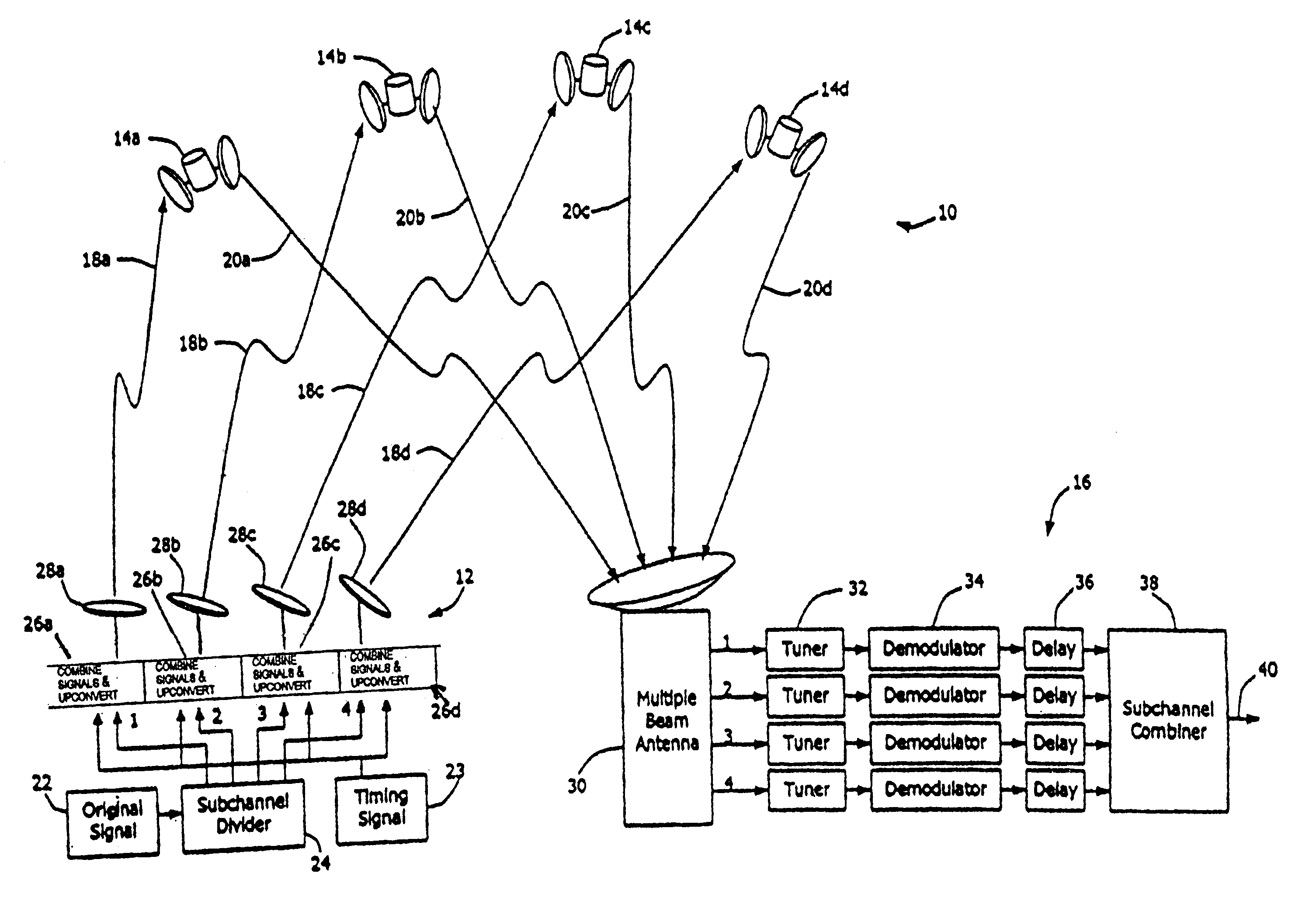
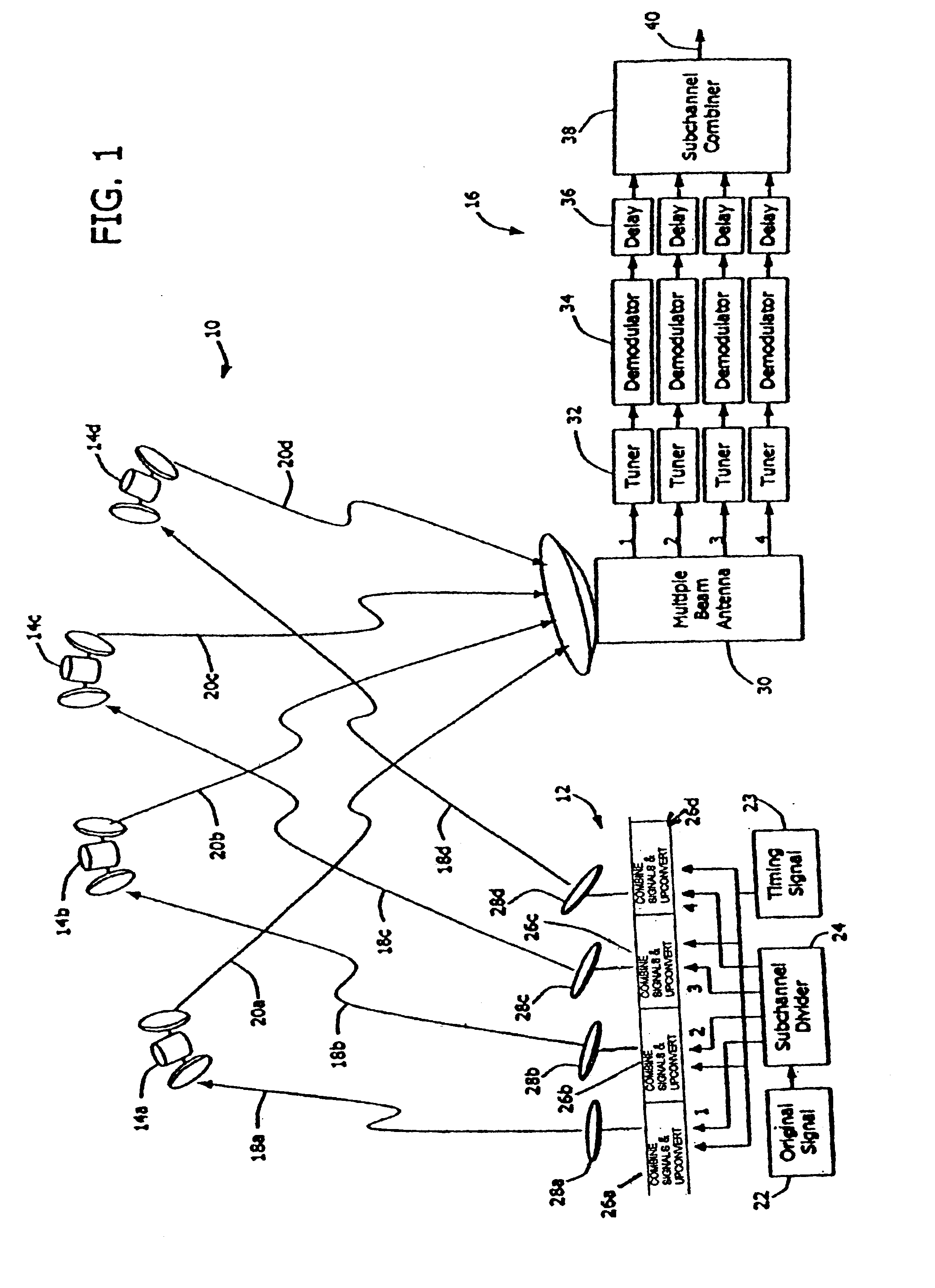
Referring now to the drawings in which like reference numerals indicate like or corresponding elements over the several views, FIG. 1 shows an overview of the satellite communications system consisting of subsystems 12, 10, 16. Original signal 22 feeds subchannel divider 24 which separates the signal into a plurality of numbered subsignals. The exemplary system of FIG. 1 shows the number of subsignals to be four, but the present invention is not so limited. Subchannel divider 24 creates the subsignals by dividing original signal 22 employing one of two methods. A first method divides the signal on the basis of power. In this first method all the subchannel signals emerging from subchannel divider 24 are identical. A second method divides the signal on the basis of content. In this second method, each subchannel signal carries at least some information that is not carried by the other subchannels. The information content may be mutually exclusive or may overlap between subchannels, b...


PUM


Abstract

A satellite communications system provides an information channel between remotely located transmitters and receivers. A virtual satellite system provides the same service, but divides the signal either in power or in data content into subchannels such that any particular signal is conducted to the intended receiver via a plurality of traditional satellite channels. The receiving terminal accepts the plurality of signals simultaneously from a possible plurality of satellites, combining the subchannels comprising the virtual channel into the original signal content as if conducted via a single channel. The receiving antenna system receives satellite subchannel signals from a plurality of directions using multiple antennas or a single antenna with multi-direction capability. Prior to signal combining, the receiver necessarily time-synchronizes the plurality of subchannels by introducing time delay in some channels before combining the subsignals into the original composite. A timing signal present in the virtual satellite system assists the receiver in determining the amount of delay to apply to each incoming signal. The timing signal is either a separate carrier or an additional modulation on the existing information-bearing carrier.

Description

BACKGROUND OF THE INVENTIONThe invention relates to satellite communications systems generally, and more particularly to satellite communication systems which divide the transmitted signal, either in power or in content, to be synchronized and recombined in the receiving terminal. This concept applies readily to broadcast applications, but it is not so limited.The satellite industry has experienced a progression of performance enhancements evidenced by increased transmit power capability of satellite transponders, improved low-noise amplifier (LNA) characteristics, and smaller receiving antennas. In satellite systems with a large number of receiving stations, it is particularly important to reduce the cost of each receiving unit and to design a system with a small receiving antenna to meet installation and aesthetic requirements. The need for a small receiving antenna has motivated an increase in transponder power output in order to maintain an acceptable signal-to-noise ratio (SNR)...

Claims


Application Information

Patent Timeline
IPC IPC(8): H04B7/185
CPCH04B7/18515
Inventor FRIEDMAN, ROBERT F.
Owner VIRLITE COMM LIMITED LIABILITY
Why Eureka
Try Eureka