Slotted injection nozzle and low NOx burner assembly

a technology of injection nozzle and nox burner, which is applied in the direction of lighting and heating apparatus, combustion types, and combustion using lump and pulverulent fuel, etc., can solve the problems of limited fuel supply pressure, high fuel and/or oxidant supply pressure, and the inability to use all low nosub>x/sub>burner designs or heating applications

Inactive Publication Date: 2005-03-15
AIR PROD & CHEM INC
View PDF26 Cites 78 Cited by
  • Summary
  • Abstract
  • Description
  • Claims
  • Application Information

AI Technical Summary

Benefits of technology

In one of several embodiments, the invention is a nozzle comprising a nozzle body having an inlet face, an outlet face, and an inlet flow axis passing through the inlet and outlet faces, and two or more slots extending through the nozzle body from the inlet face to the outlet face, each slot having a slot axis. The slot axis of at least one of the slots is not parallel to the inlet flow axis

Problems solved by technology

If the nozzle design geometry is not optimized, the nozzle may require much higher fuel and/or oxidant supply pressures or higher average gas velocities to achieve proper mixing in the furnace and yield the required NOx emission levels.
In many processes in the chemical industry, the fuel supply pressure is limited due to upstream or downstream processes.
However, these methods cannot

Method used


Image

  • Slotted injection nozzle and low NOx burner assembly
  • Slotted injection nozzle and low NOx burner assembly
  • Slotted injection nozzle and low NOx burner assembly

Examples


example

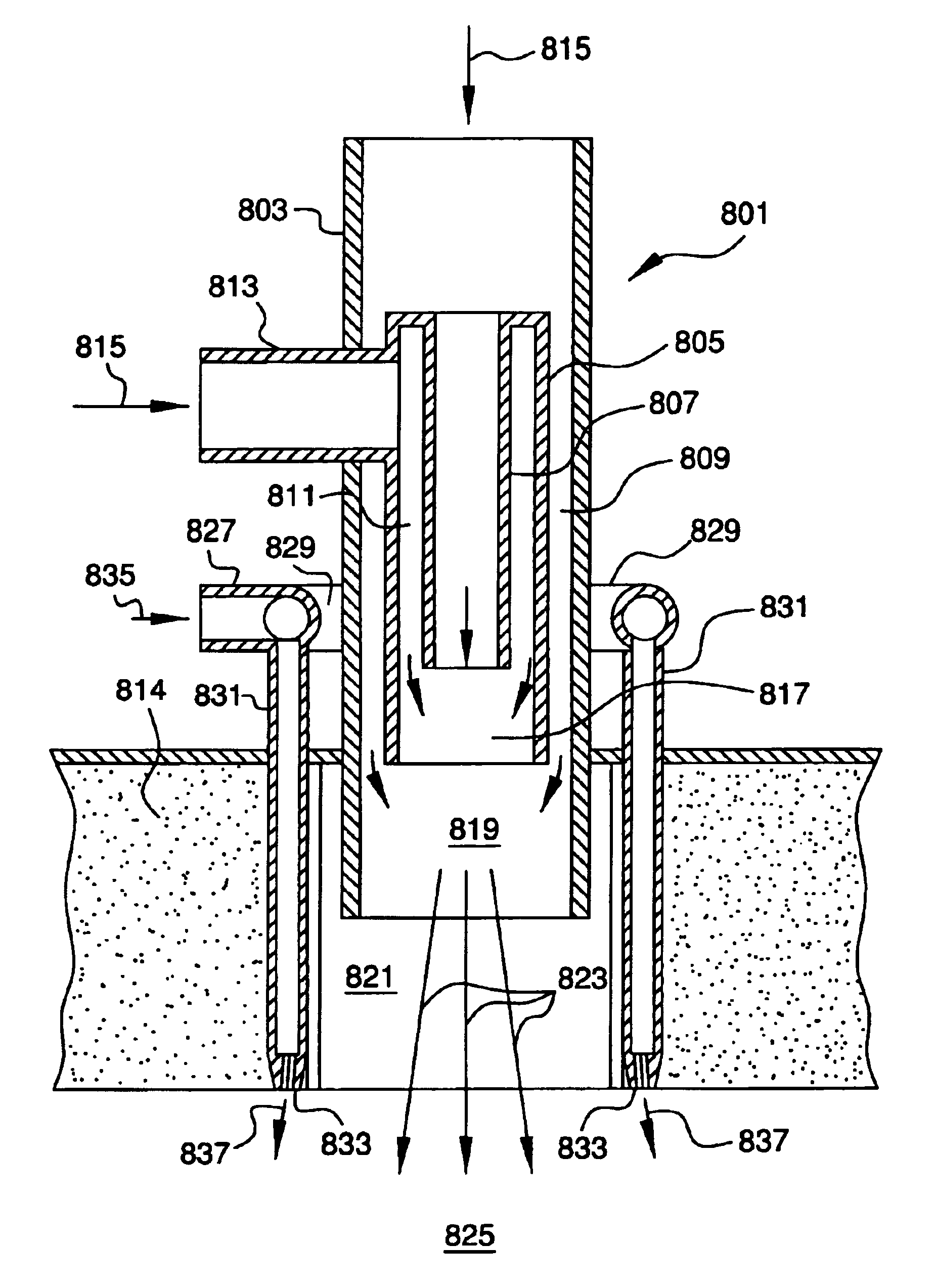
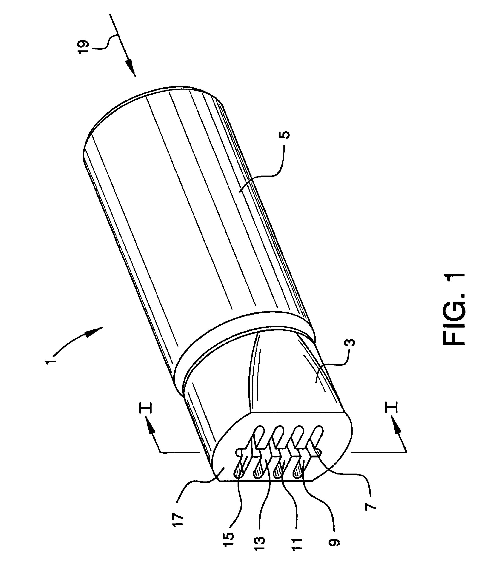
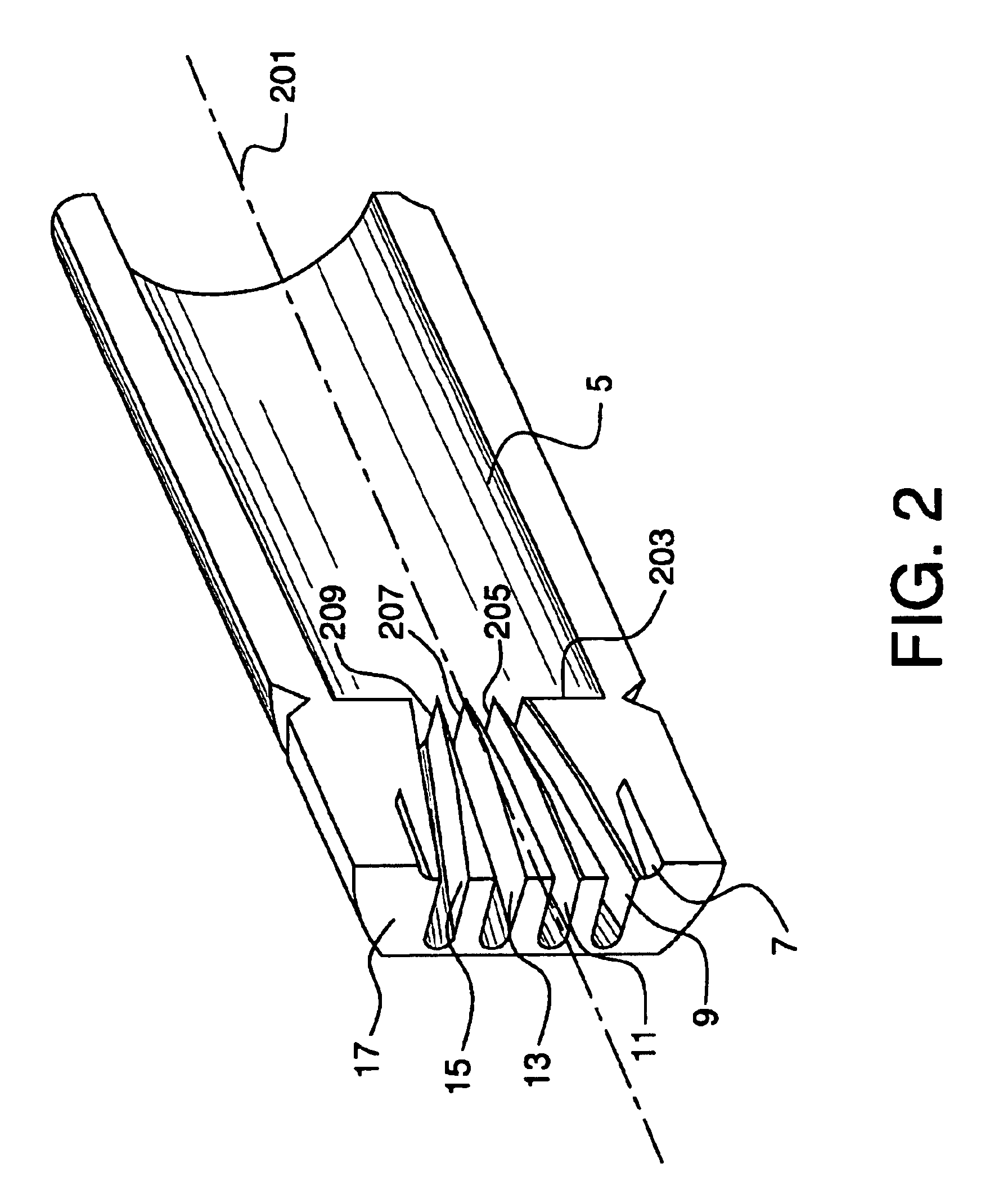
A combustion test furnace utilizing the burner assembly of FIGS. 8 and 9 was operated to compare the performance of the nozzles of FIGS. 1 and 4 with a circular nozzle configuration illustrated in FIGS. 10A, 10B, and 10C. These nozzles may be defined as staging nozzles which deliver secondary fuel to a second stage of combustion, wherein the fuel for the first stage of combustion is provided by fuel 815 via pipe 813 of FIG. 8.

The test furnace was 6 ft by 6 ft in cross-section and 17 ft long, had a burner firing at one end, and had an outlet for the combustion products at the other end. The outlet was connected to a stack fitted with a damper for furnace pressure control. The interior of the furnace was lined with high-temperature refractory and had water-cooled panels to simulate furnace load. The test burner was fired in the range of 3 to 6 MMBTU / hr using natural gas for the primary fuel and the secondary (staging) fuel. The flow rate of natural gas was varied between 3000 SCFH and...


PUM


Abstract

A nozzle comprising a nozzle body having an inlet face, an outlet face, and an inlet flow axis passing through the inlet and outlet faces, and two or more slots extending through the nozzle body from the inlet face to the outlet face. Each slot has a slot axis and the slot axis of at least one of the slots is not parallel to the inlet flow axis of the nozzle body. In another embodiment, the nozzle comprises a nozzle body having an inlet face, an outlet face, and an inlet flow axis passing through the inlet and outlet faces, and two or more slots extending through the nozzle body from the inlet face to the outlet face, each slot having a slot axis, wherein none of the slots intersect other slots and all of the slots are in fluid flow communication with a common fluid supply conduit. The nozzles may be used to inject secondary fuel in a burner system having a central burner combusting a primary fuel surrounded by secondary fuel injection nozzles.

Description

BACKGROUND OF THE INVENTIONNozzles are used in a wide variety of applications to inject one fluid into another fluid and promote efficient mixing of the two fluids. Such applications include, for example, chemical reactor systems, industrial burners in process furnaces, fuel injectors in gas turbine combustors, jet engine exhaust nozzles, fuel injectors in internal combustion engines, and chemical or gas injection in wastewater treatment systems. The objective in these applications is to promote vortical mixing and rapid dispersion of the injected fluid into the surrounding fluid. It is usually desirable to achieve this efficient mixing with a minimum pressure drop of the injected fluid.The proper design of injection nozzles for burners in industrial furnaces and boilers is important for maximizing combustion efficiency and minimizing the emissions of carbon monoxide and oxides of nitrogen (NOx). In particular, tightening regulations on NOx emissions will require improved and highly...

Claims


Application Information

Patent Timeline
IPC IPC(8): F23D14/58F23D14/48
CPCF23D14/583F23C2201/30F23D2203/1023
Inventor LADHARAM, MAHENDRA
Owner AIR PROD & CHEM INC
Why Eureka
Try Eureka