Contact slidable structure with a high durability

Active Publication Date: 2005-03-15
DENSO CORP
View PDF32 Cites 24 Cited by
  • Summary
  • Abstract
  • Description
  • Claims
  • Application Information

AI Technical Summary

Benefits of technology

It is another object of the invention to provide a contact slidable

Problems solved by technology

However, heretofore, the following problems are known to arise in case of using the resilient terminal having the above structure.
More specifically, strength of the terminal electrode is deteriorated at the portion thereof where the conductive t

Method used


Image

  • Contact slidable structure with a high durability
  • Contact slidable structure with a high durability
  • Contact slidable structure with a high durability

Examples


Example

First Embodiment

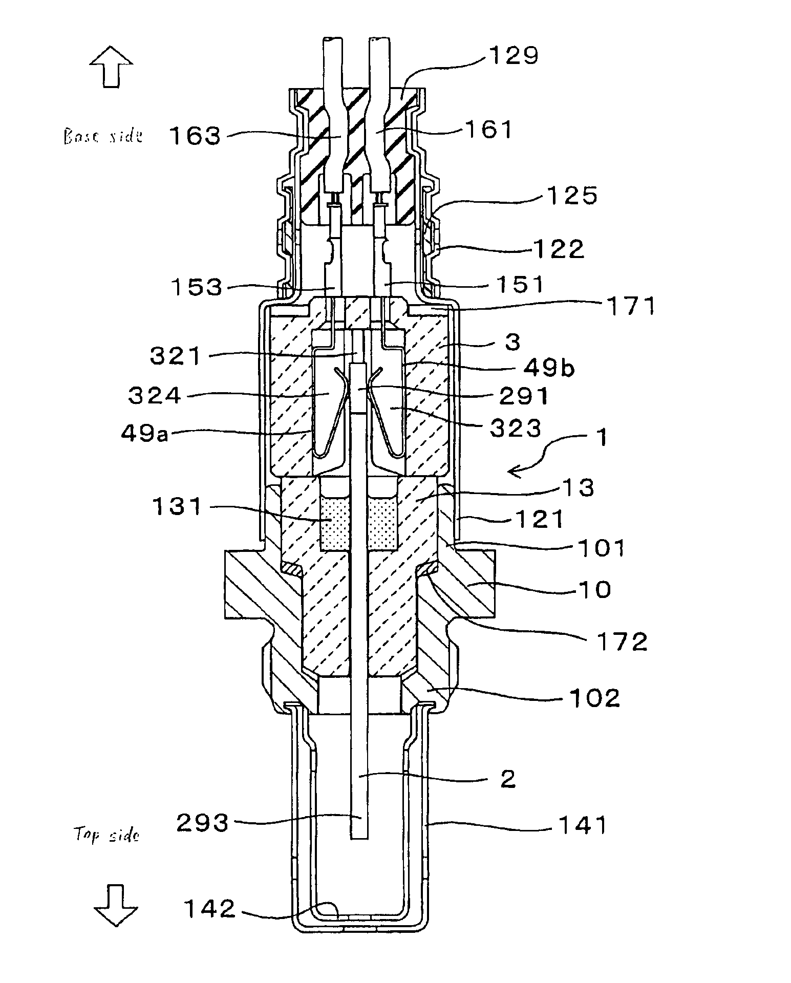
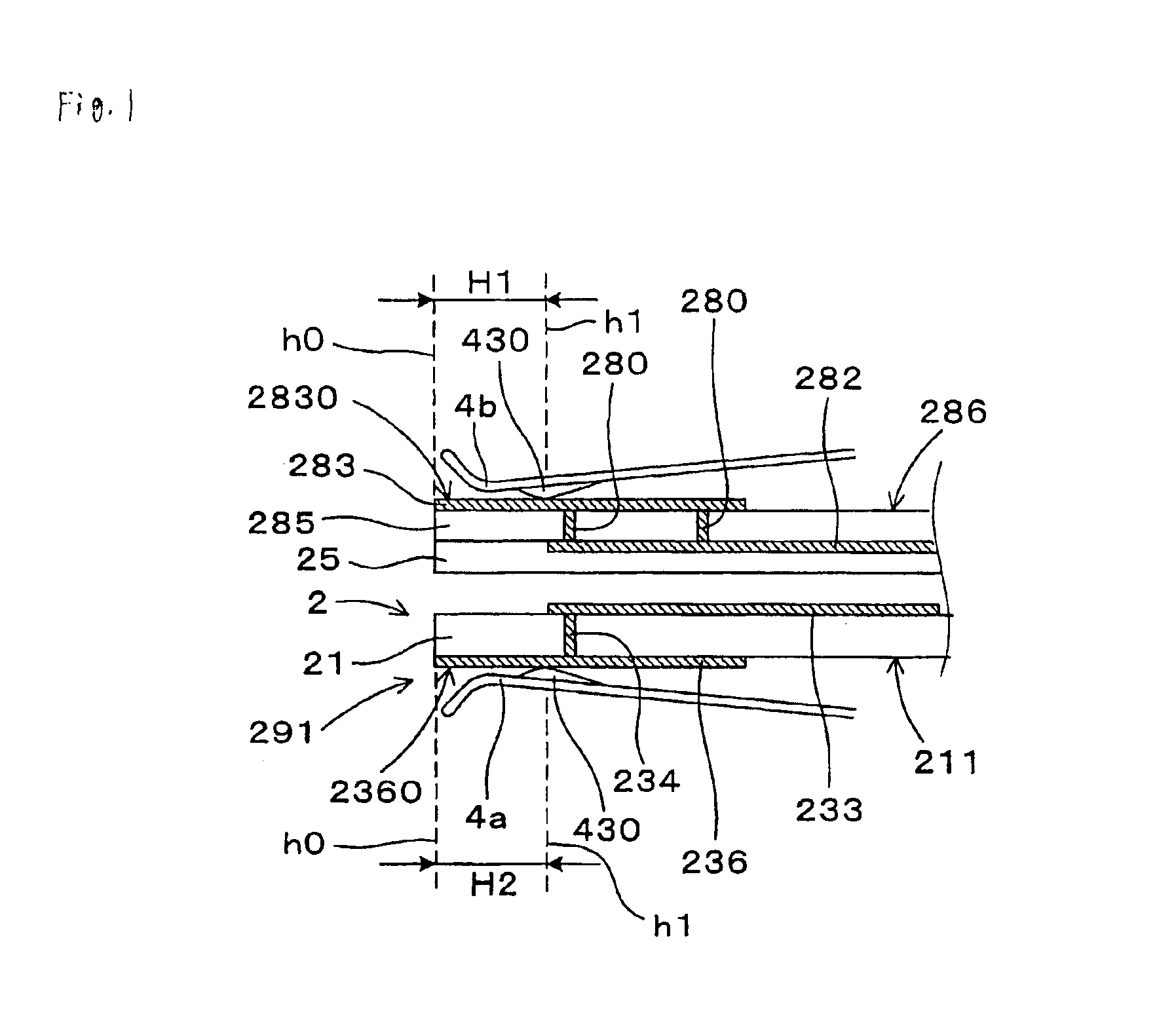
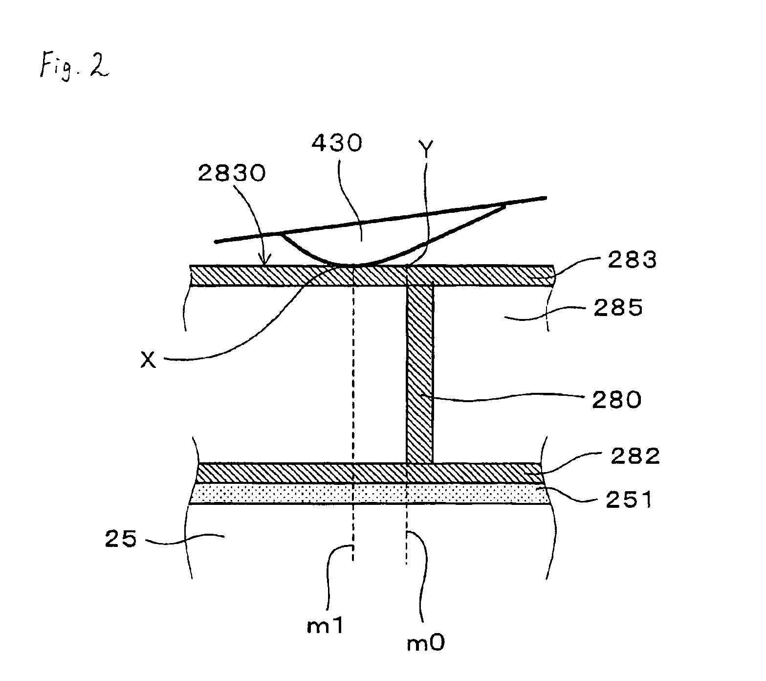
As shown in FIGS. 1-11, the contact slidable structure formed between the ceramic element 2 and the resilient terminals 4a,4b,49a and 49b includes the ceramic body 20, the inner leads 282 and 233 build in the ceramic body 20, the terminal electrodes 283 and 236 formed on an upper surface of the ceramic body 20, and the conductive through holes 280 and 234 extending through the inner leads 282 and 233 and the terminal electrodes 283 and 236, respectively, to form an electrical connection therebetween, in which the resilient terminals 4a,4b,49a and 49b are placed to be slidable on the upper surface 2830 and 2360 of the terminal electrodes 283 and 236, respectively. The conductive through holes 280 and 234 are not formed within the contact slidable areas H1 and H2 where the resilient terminals 4a,4b,49a and 49b are slidable on the terminal electrodes 283 and 236, respectively.

As shown in FIG. 6, the ceramic element 2 works as a gas sensing element which has the single e...

Example

Second Embodiment

In the second embodiment, as shown in FIGS. 12A and 12B, a contact slidable structure is formed between the ceramic element 5 and the resilient terminal 59a.

The ceramic element 5 includes the ceramic body 50, the inner lead 501, and the conductive through hole 52. The resilient terminal 59a has a width identical with or more than that of the ceramic element 5.

As shown in FIG. 12B, the contact slidable area H3 extends over the ceramic element 5 in a lateral direction thereof, indicated by the sign W. As shown in FIG. 12B, the contact slidable area H3 is defined as a square area by the dotted lines a1 and a2, i.e. the surfaces of the terminal electrode 51 and the ceramic body 50 between the dotted line a1 on which the resilient terminal 59 comes into contact with the terminal electrode 51 and the dotted line 2 on which the resilient terminal 59 stops, upon joining the ceramic element 5 with the resilient terminal 59. Thus, as shown in FIGS. 12A and 12B, the conductiv...

Example

Third Embodiment

The third embodiment of the invention will be described.

In this embodiment, as shown in FIG. 13, the width of the resilient terminal (not shown) is narrower than that of the ceramic element 55. The width of the contact slidable area is equivalent to the width of the resilient terminal (not shown), and the contact slidable area is indicated by sign B surrounded by a dotted line in FIG. 13.

The contact slidable area B is selected, so that the conductive through hole 52 is out of alignment to the contact slidable area B in a lateral direction of the ceramic element 55, or leftward of the contact slidable area B in FIG. 13.

In other words, the conductive through hole 52 may be formed leftwards or outside the contact slidable area B in the lateral direction of the ceramic element 55.

The rest of the arrangement of the third embodiment is substantially identical with that of the first embodiment. Hence, the third embodiment brings substantially the same functions and effects....


PUM


Abstract

A contact slidable structure is formed between a resilient terminal and a terminal electrode. The terminal electrodes and are disposed on the ceramic element. The resilient terminals and are resiliently deformed and forced to press the terminal electrodes and. The ceramic element has the ceramic body, inner leads and formed inside the ceramic body, terminal electrodes and disposed on the outer surfaces and, and conductive through holes and electrically connecting the inner leads and with the terminal electrodes and, respectively. In the ceramic element, the resilient terminals and are placed slidably on the outer surfaces and of the terminal electrodes and to form the contact slidable structure, and the conductive through holes and are not formed within the contact slidable areas and to the terminal electrodes and, respectively.

Description

BACKGROUND OF THE INVENTION1. Technical Field of the InventionThe present invention relates generally to a contact slidable structure formed by a resilient terminal and a terminal electrode of a ceramic element such as a gas sensing element used in a gas sensor capable of measuring concentration of a predetermined component contained in an automotive exhaust gas.2. Background ArtIn an exhaust gas system of an automotive internal combustion engine, a gas sensor for measuring concentration of a predetermined component, such as oxygen gas, NOx and others, is installed to control combustion in the engine and to detect deterioration in a catalyst installed in the automotive exhaust gas system.Japanese Patent Application Laid-open No.2002-286681 and U.S. Pat. No. 6,447,887 (Japanese Patent Application Laid-open No.2001-188060) disclose conventional gas sensing element.As a type of the gas sensing element being installed in the gas sensor, a build-up gas sensing element having the structur...

Claims


Application Information

Patent Timeline
IPC IPC(8): G01N27/407G01N27/41F01N11/00F02D41/14H01R4/48H01R13/24H01R24/00H01R24/58H01R41/00
CPCH01R12/721G01N27/407
Inventor KIMATA, TAKEHITOSATO, YASUYUKI
Owner DENSO CORP
Why Eureka
Try Eureka