Enhanced method for joining two core wires

a core wire and core wire technology, applied in the direction of guide wires, catheters, diagnostic recording/measuring, etc., can solve the problems of high cost of nitinol hypotubes or connecting tubes, and achieve the effect of small or no stiffness and sufficient column strength

Inactive Publication Date: 2005-03-15
ABBOTT CARDIOVASCULAR
View PDF20 Cites 102 Cited by
  • Summary
  • Abstract
  • Description
  • Claims
  • Application Information

AI Technical Summary

Benefits of technology

In one embodiment, the invention provides a core having a proximal core section with a proximal end and a distal end and a distal core section with a proximal end and a distal end. It is preferred that the proximal core section is made of stainless steel to provide sufficient column strength, and the distal core section is made of nitinol which is flexible to advance through a tortuous body lumen. The distal end of the proximal core section and the proximal end of the distal core section are plunge ground to a smaller diameter, and then the ends are tapered. It is possible, however, to form the distal end of the proximal core section and the proximal end of the distal core section into any complementary shape, such as those disclosed in the '873 application. The ends are then placed into a sleeve in opposing directions such that the two tapered surfaces face each other and the ends overlap one another. The sleeve may be either a spring coil, a polymeric sleeve, such as a polyimide sleeve or tube, a patterned tube, or other flexible polymer or metallic material that can accommodate the two ends. The sleeve material has essentially little or no stiffness, especially when compared to a nitinol hypotube. A mass of hardened material, such as solder or glue, is used to join the assembly together. Once bonded, the outer diameter of the sleeve is the same as or similar to that of the core wire, thereby eliminating the need for post-bonding procedures, such as grinding to achieve a desired outer diameter.

Problems solved by technology

Currently, an expensive nitinol hypotube or connecting tube is used to join a proximal stainless steel core to a nitinol distal core on certain types of guide wires.

Method used


Image

  • Enhanced method for joining two core wires
  • Enhanced method for joining two core wires
  • Enhanced method for joining two core wires

Examples


Embodiment Construction

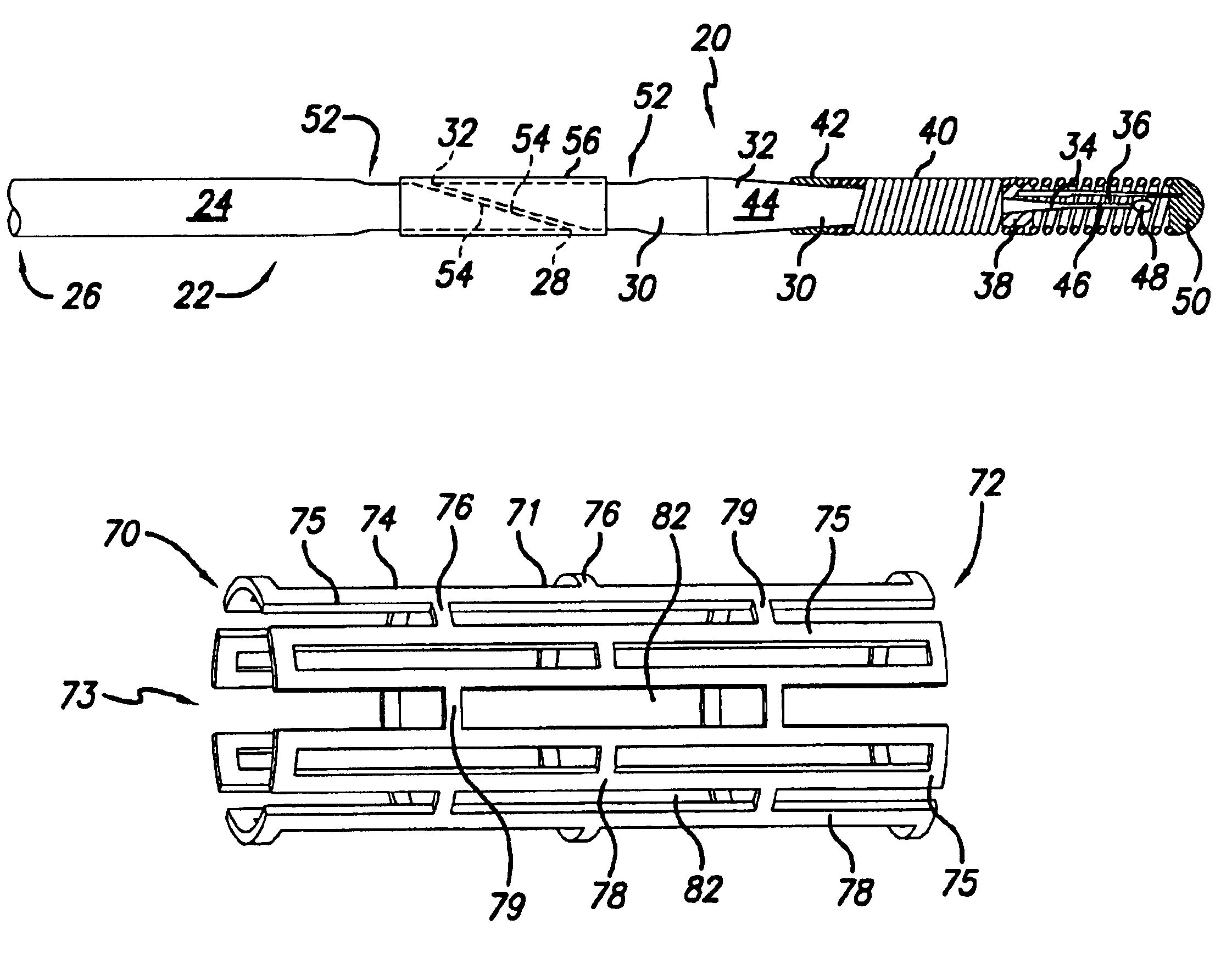
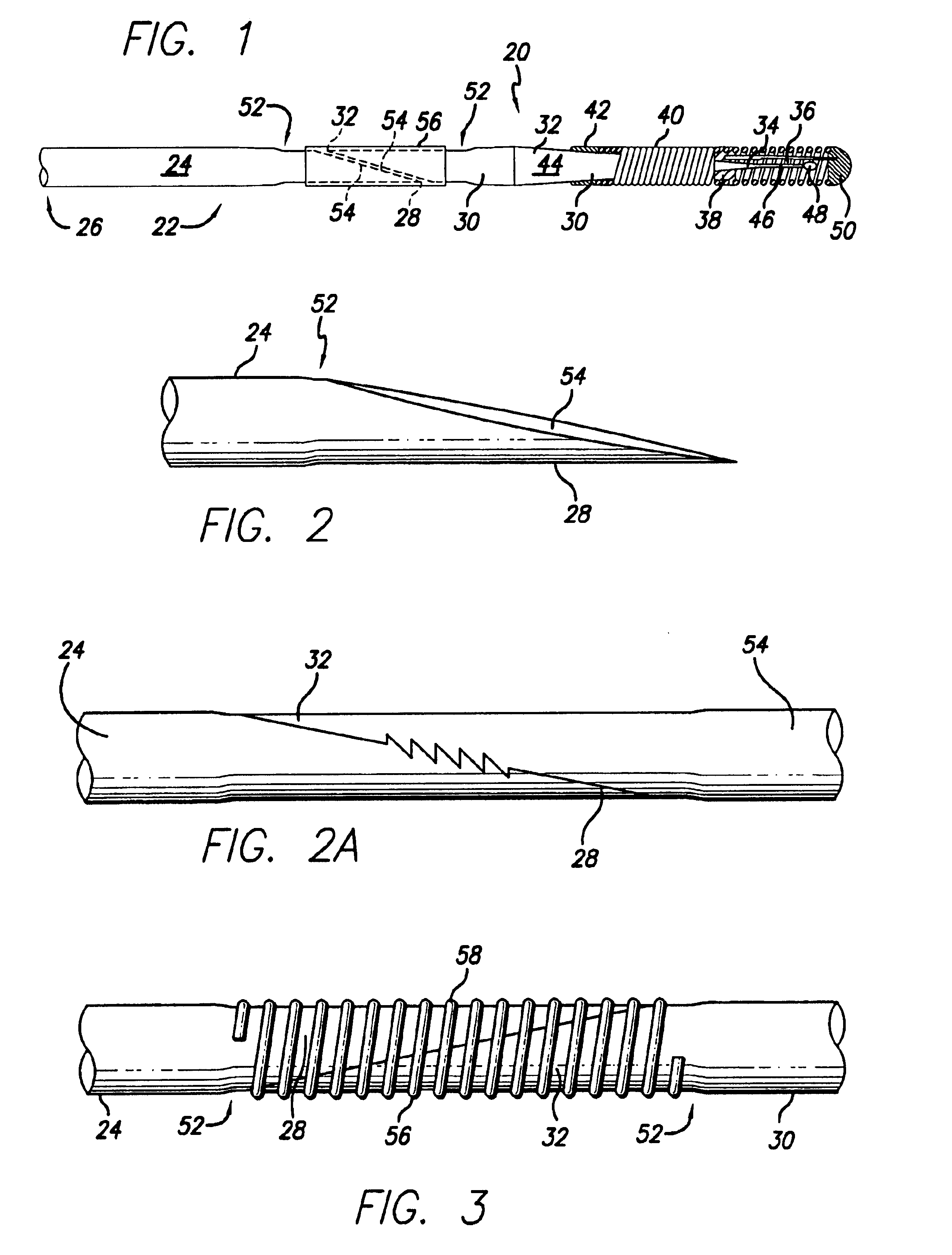
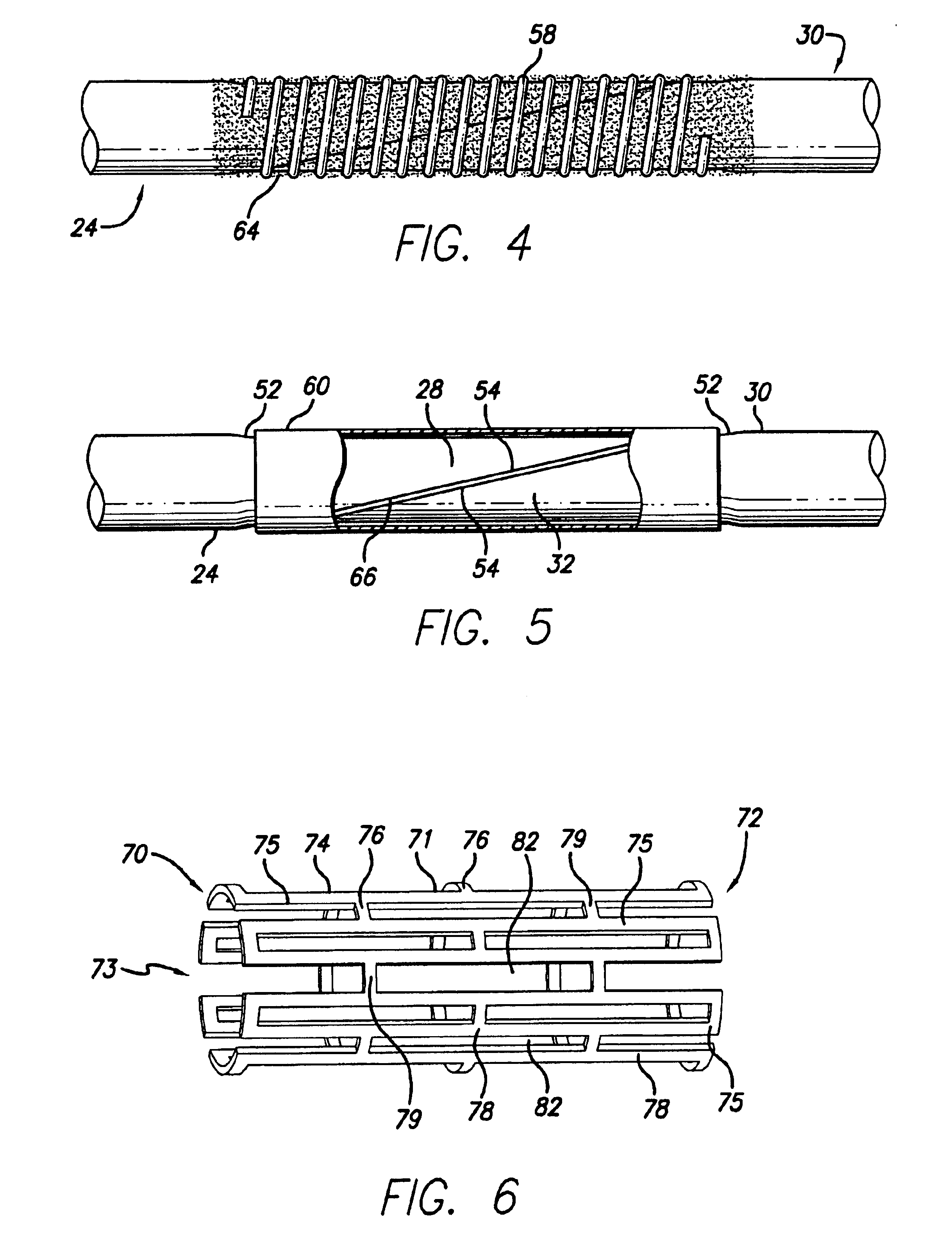
The present invention is directed to a guide wire that uses at least two core materials that are joined at an interface. FIG. 1 illustrates in a side elevational view one embodiment of the present invention guide wire, generally designated 20, that is adapted for insertion into a patient's body lumen, such as an artery or vein. In this embodiment, the intravascular guide wire 20 has at least two core materials joined or secured together. In particular, the guide wire 20 has a core 22 with a proximal core section 24 having a proximal end 26 and a distal end 28, and a distal core section 30 having a proximal end 32 and a distal end 34. It is preferred that the proximal core section 24 is made of stainless steel, and the distal core section 30 is made of nitinol. However, the core sections may be made out of any material known in the guide wire art.

In the embodiment as shown in FIG. 1, the guide wire 20 also includes a shapeable member 36 which can be secured to the distal core section...


PUM

PropertyMeasurementUnit
diameteraaaaaaaaaa
outer diameteraaaaaaaaaa

Abstract

An intravascular guide wire having at least two core materials joined together. There is a wire core having a proximal core section with a proximal end and a distal end and a distal core section with a proximal end and a distal end. The distal end of the proximal core section and the proximal end of the distal core section are formed into complementary shapes, and then placed into a flexible sleeve in opposing directions. Inside the flexible sleeve, the complementary shaped ends are joined together through bonding, welding, brazing, cementing, or soldering. The flexible sleeve can be either a stretched coil or a polyimide sleeve, each with an outer diameter similar to the outer diameter of the core wire, therefore the guide wire does not require additional grinding to reduce the outer diameter of the joined section.

Description

BACKGROUND OF THE INVENTIONThis invention relates to the field of medical devices, and more particularly to a guide wire for advancing a catheter within a body lumen in a procedure such as percutaneous transluminal coronary angioplasty (PTCA).In a typical PTCA procedure, a guiding catheter having a pre-formed distal tip is percutaneously introduced into a patient's peripheral artery, e.g. femoral or brachial artery, by means of a conventional Seldinger technique and advanced therein until the distal tip of the guiding catheter is seated in the ostium of a desired coronary artery. A guide wire is first advanced by itself through the guiding catheter until the distal tip of the guide wire extends beyond the arterial location where the procedure is to be performed. Then a catheter is mounted onto the proximal portion of the guide wire which extends out of the proximal end of the guiding catheter which is outside of the patient. The catheter is advanced over the guide wire, while the po...

Claims


Application Information

Patent Timeline
Patent Type & Authority Patents(United States)
IPC IPC(8): B21F15/06B21F15/08B21F15/00F16G11/00F16G11/08A61M25/09
CPCA61M25/09F16G11/08B21F15/08B21F45/008B21F15/06A61M2025/09108
Inventor KELLERMAN, BRADSPECK, MARC L.
Owner ABBOTT CARDIOVASCULAR
Why Eureka
Try Eureka