Virtual image registration in augmented display field

a virtual image and display technology, applied in static indicating devices, instruments, optical elements, etc., can solve problems such as drifting errors in the innermost tracker, and achieve the effects of accurate positioning, increased overall update of the hybrid system, and more accurate prediction

Inactive Publication Date: 2005-03-15
UNIV OF WASHINGTON
View PDF15 Cites 206 Cited by
  • Summary
  • Abstract
  • Description
  • Claims
  • Application Information

AI Technical Summary

Benefits of technology

A time at which a detector is temporally located in the horizontal scanning axis is derived as occurring one half way between the first time and the second time. The location of the detector in the vertical scanning axis (line) is determined within a scan frame by measuring time duration from the beginning of the frame (VSYNC) to a time at which the tracking light impinges on the detector. By determining a location independently from the temporal resolution of the augmented imaging system, the temporal location of the detector is identified to a sub-pixel/sub-line precision. By deriving the detector location in this manner, the detector is accurately located even in the presence of characteristic changes in the mechanical resonant scanner (MRS).
One detector in each pair serves as a reference whose location is identified. The other detector in each pair is used to determine the direction at which the...

Problems solved by technology

The inertial tracker i...

Method used


Image

  • Virtual image registration in augmented display field
  • Virtual image registration in augmented display field
  • Virtual image registration in augmented display field

Examples


Embodiment Construction

Overview

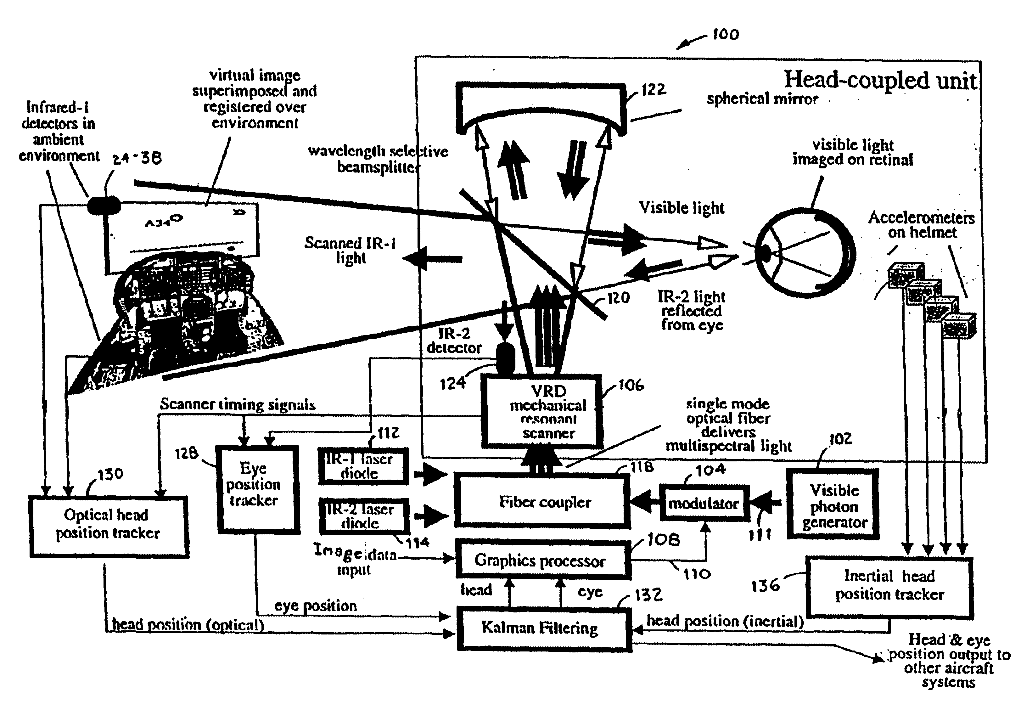
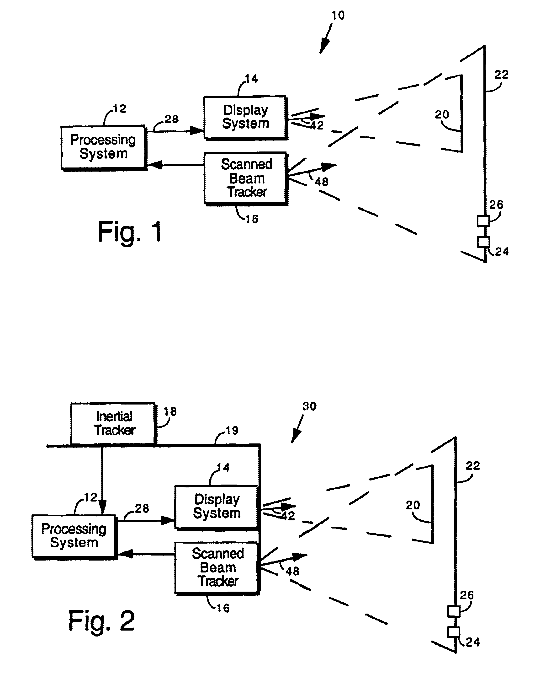
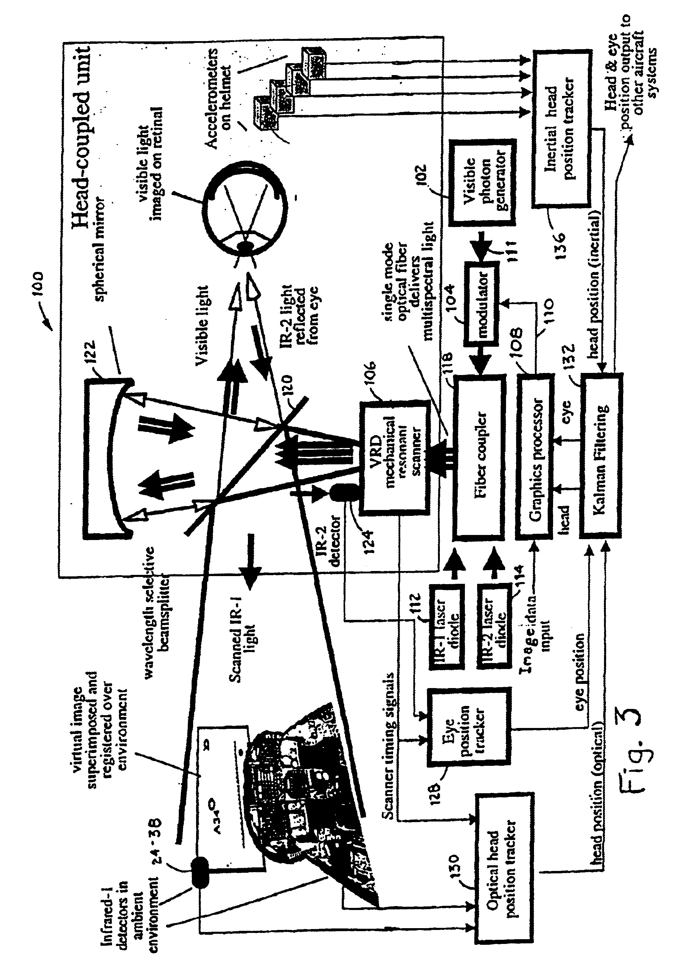
FIGS. 1 and 2 show alternative embodiments for an augmented reality imaging system. The augmented reality imaging system 10 of FIG. 1 includes optical tracking to provide accurate augmented image registration relative to the real world background. The augmented reality imaging system 30 of FIG. 2 includes hybrid tracking to provide accurate augmented image registration relative to the real world background. The hybrid tracking includes optical tracking and inertial tracking implementing a higher tracking update rate.

An objective of an augmented reality imaging system is to enhance human interaction with the real world using computer-generated information that is related to real world objects. For example, in a bioengineering application augmented reality information is beneficial in guiding a surgeon during a needle biopsy. The surgeon can look directly at the patient while the augmented imaging system projects an ultrasound image over the real one, allowing for simultaneous...


PUM


Abstract

A virtual image is registered among a perceived real world background. Tracking light is scanned into the real world environment, which includes at least one detector pair. A first time and a second time at which the tracking light impinges on the first detector is detected, in which the first time and second time occurs within adjacent scan lines. A time at which a horizontal scan line edge (e.g., beginning of scan line or end of scan line) is encountered is derived as occurring one half way between the first time and the second time. The horizontal location of the first detector then is determined within a specific scan line inferring the scan line edge time. The vertical location of the detector is determined within a scan frame by measuring time duration using the beginning of the frame. By determining a location independently from the temporal resolution of the augmented imaging system, the temporal location of the detector is identified to a sub-pixel/sub-line precision. The augmented image is registered either to a 3D real world spatial coordinate system or to a time domain coordinate system based upon tracked position and orientation of the user.

Description

BACKGROUND OF THE INVENTIONThe present invention is directed to an augmented imaging system with tracking capability. In an augmented imaging system virtual images are rendered over a real-world background. In an augmented retinal imaging system, for example, the real world background light is viewed while virtual imagery is scanned onto a viewer's retina. The viewer sees the virtual imagery among the real world background scene.SUMMARY OF THE INVENTIONA virtual image is registered among a perceived real world background. Tracking light is scanned into the real world environment, which includes at least one pair of detector surfaces. A first time and a second time at which the tracking light impinges on a first detector surface is detected, in which the first time and second time occurs within adjacent scan lines, typically scanned in opposite directions (e.g., a first scan line and a corresponding return scan line; a return scan line and a subsequent next scan line). The pair of de...

Claims


Application Information

Patent Timeline
IPC IPC(8): G06F3/00G06F3/01
CPCG06F3/011
Inventor CHINTHAMMIT, WINYUSEIBEL, ERICFURNESS, III, THOMAS A
Owner UNIV OF WASHINGTON
Why Eureka
Try Eureka