Photosensor system and drive control method thereof

a technology of drive control and photosensor, which is applied in the field of photosensor system to achieve the effect of accurately reading a subject imag

Inactive Publication Date: 2005-03-15
CASIO COMPUTER CO LTD
View PDF21 Cites 15 Cited by
  • Summary
  • Abstract
  • Description
  • Claims
  • Application Information

AI Technical Summary

Benefits of technology

[0022]It is an object of the present invention to provide a reading sensitivity setting method of unconditionally and automatically setting a proper image reading sensitivity in order to accurately read a subject image in various use environments in a...

Problems solved by technology

(1) To read a subject image in various use environments in a photosensor system using the above-described photosensor, the image reading sensitivity (charge accumulating period) must be properly set. The proper image reading sensitivity changes depending on changes in ambient conditions such as the illuminance of external light in a use environment, and also changes when the characteristics of the photosensor change. In the prior art, therefore, a circuit for detecting the illuminance of external light must be additionally arra...

Method used


Image

  • Photosensor system and drive control method thereof
  • Photosensor system and drive control method thereof
  • Photosensor system and drive control method thereof

Examples


seventh embodiment

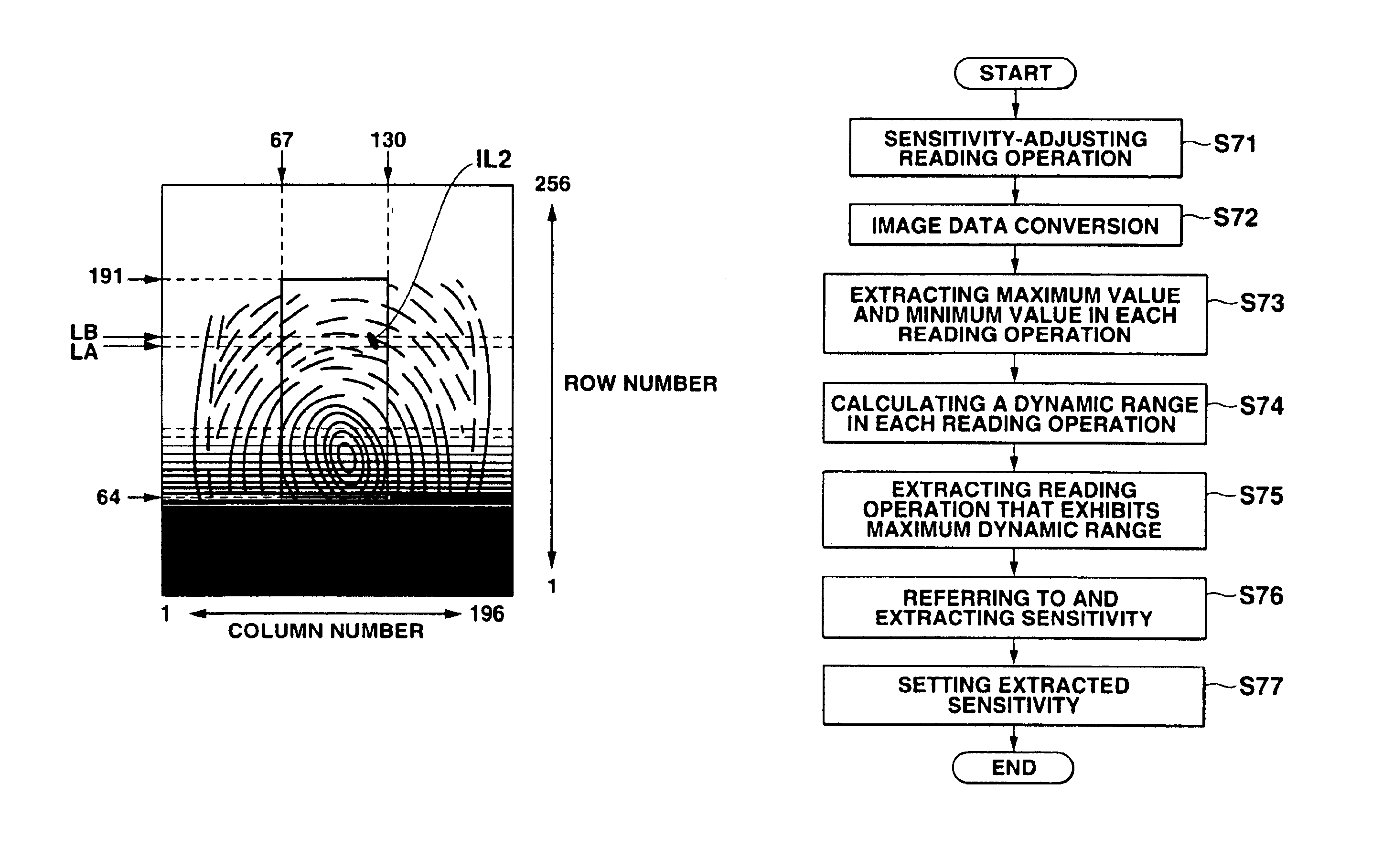
[0061]FIG. 32 is a flowchart illustrating operation of the seventh embodiment;

[0062]FIG. 33 shows a specific row section of a photosensor array for which sensitivity-adjusting reading operation is performed according to the seventh embodiment, the specific row section being illustrated in relation to a subject image;

[0063]FIGS. 34A to 34E are graphs showing how lightness data on a specific row section changes in the seventh embodiment, in relation to the number of times the reading operation is performed; FIGS. 35A to 35J are timing charts showing the first embodiment of an image reading sensitivity setting method applied to sensitivity-adjusting reading operation executed in each of the first to fifth embodiments;

[0064]FIGS. 36A to 36J are timing charts showing the second embodiment of an image reading sensitivity setting method applied to sensitivity-adjusting reading operation executed in each of the first to fifth embodiments;

[0065]FIGS. 37A to 37L are timing charts illustrating...

first embodiment

[0079]the photosensor system drive control method according to the present invention will be described with reference to the several views of the accompanying drawing.

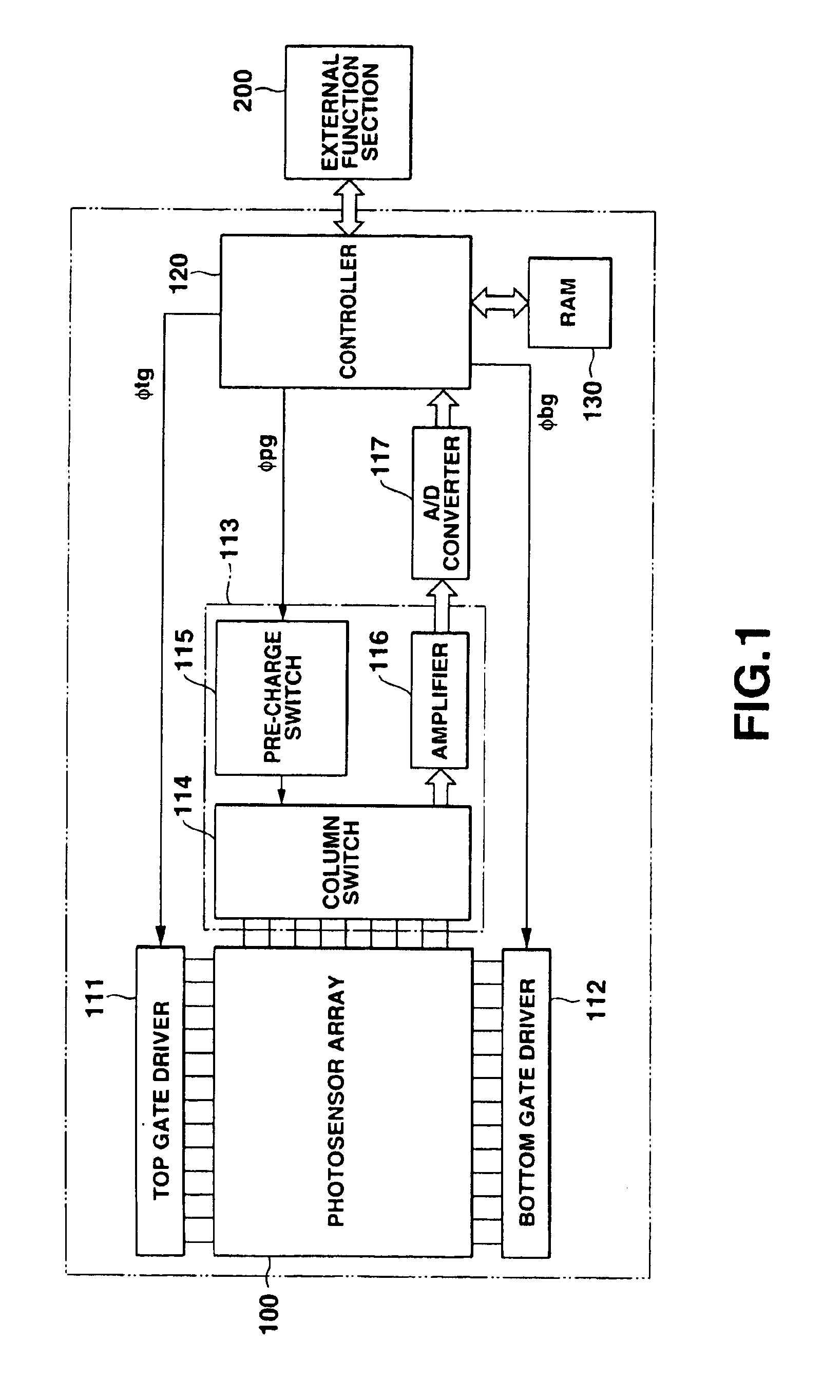
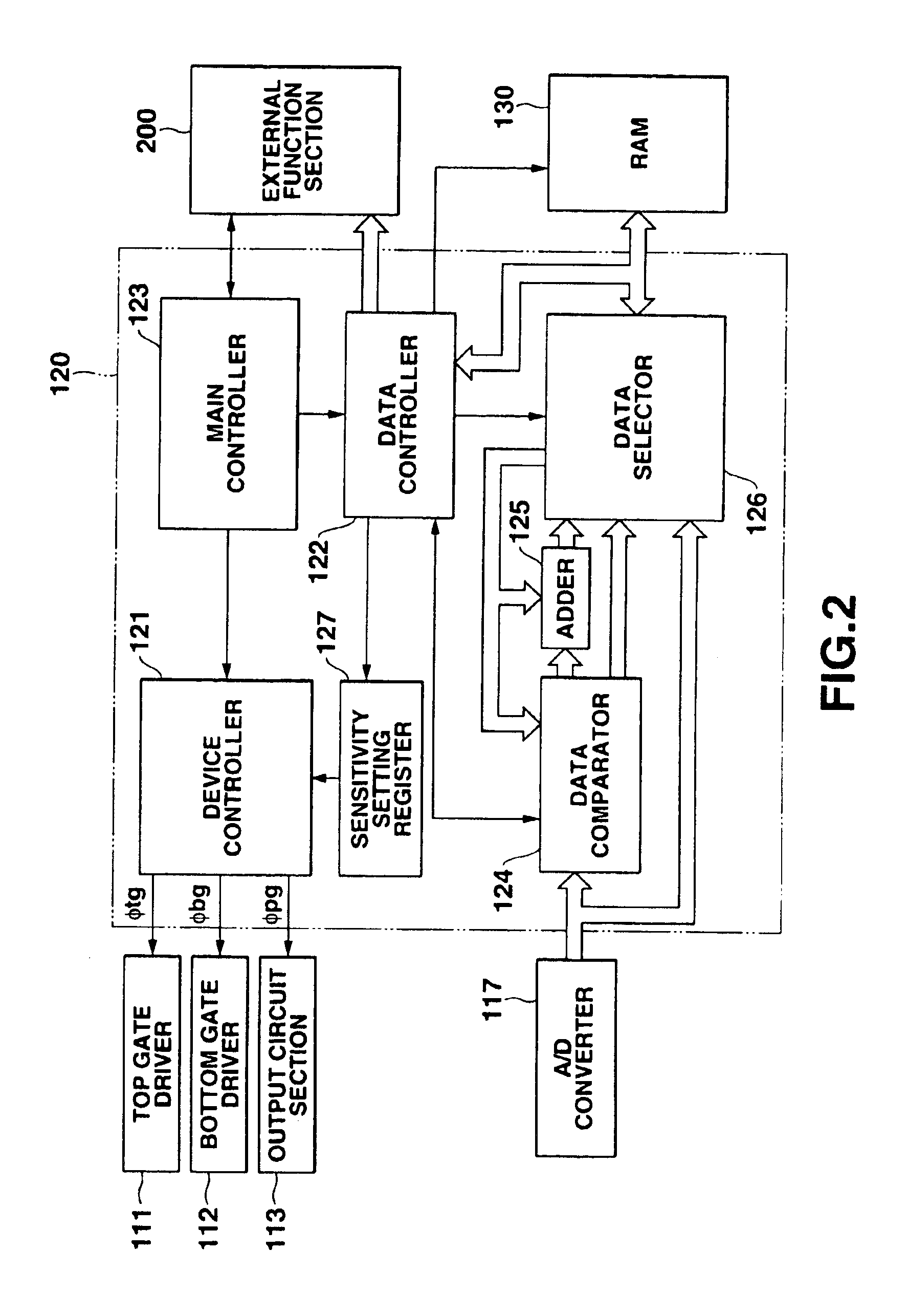
[0080]FIG. 2 is a block diagram showing an arrangement of a controller 120 applied to the first embodiment. As shown in FIG. 2, the controller 120 comprises a device controller 121 for controlling a top gate driver 111, bottom gate driver 112, and output circuit section 113, a data controller 122 for managing various data such as image data, write data, and readout data to the RAM 130, and a main controller 123 which supervises the controllers 121 and 122 and interfaces with an external function section.

[0081]The controller 120 further comprises a data comparator 124 for comparing the sizes of specific measurement data based on image data input as a digital signal from a photosensor array 100 via an A / D converter 117 to extract maximum and minimum values, an adder 125 having a function of calculating, e.g., the differe...

second embodiment

[0107]FIG. 10 is a flow chart showing an operation up to read of a subject image with an optimal sensitivity in operation control of the photosensor system. This operation will be described by properly referring to the arrangement of the photosensor system shown in FIGS. 1 and 2.

[0108]In S21 (sensitivity-adjusting reading operation) of FIG. 10, a main controller 123 controls to set an image reading sensitivity for sensitivity-adjusting reading operation in a sensitivity setting register 127 via a data controller 122, and executes the sensitivity-adjusting reading operation of reading a subject image at a plurality of different sensitivities while changing the image reading sensitivity stepwise for respective rows of the subject image. These operations are executed prior to normal reading operation of a subject image, for example. The image reading sensitivities of respective rows are stored as a row number vs. image reading sensitivity correspondence table in a RAM 130 in correspon...


PUM


Abstract

A photosensor system performs a sensitivity-adjusting reading operation with respect to a subject image, while simultaneously changing the image reading sensitivity stepwise for each of rows of a photosensor array or for specific rows thereof. The dynamic ranges of the lightness data on the read subject image are checked to see how they are distributed in relation to the image reading sensitivities. On the basis of this distribution, an image reading sensitivity that contributes to an optimal image reading state is extracted as an optimal image reading sensitivity.

Description

CROSS-REFERENCE TO RELATED APPLICATIONS[0002]This application is a continuation-in-part application of application Ser. No. 09 / 703,025, filed Oct. 31, 2000.[0003]This application is based upon and claims the benefit of priority from the prior Japanese Patent Applications No. 11-316650, filed Nov. 8, 1999; No. 11-319605, filed Nov. 10, 1999; No. 2000-015981, filed Jan. 25, 2000, and No. 2001-198615, filed Jun. 29, 2001, the entire contents of which are incorporated herein by reference.BACKGROUND OF THE INVENTION[0004]The present invention relates to a photosensor system having a photosensor array constituted by two-dimensionally arraying a plurality of photosensors, and a drive control method thereof.[0005]Imaging apparatuses such as electronic still cameras, video cameras, and the like have come to be very widely used. These imaging apparatuses employ a solid-state imaging device, such as a CCD (Charge Coupled Device), which serves as a photoelectric converting device for converting...

Claims


Application Information

Patent Timeline
IPC IPC(8): H04N5/235
CPCH04N5/2351H04N23/71
Inventor NAKAMURA, YOSHIAKIKOSHIZUKA, YASUO
Owner CASIO COMPUTER CO LTD
Why Eureka
Try Eureka