CD metrology analysis using green's function

a technology of cd metrology and function, applied in chemical methods analysis, instruments, using wave/particle radiation means, etc., can solve problems such as accelerating numerical evaluation of scattering response, and achieve the effect of enhancing efficiency, efficient method for modeling optical diffraction, and enhancing efficiency

Inactive Publication Date: 2005-03-15
THERMA WAVE INC
View PDF8 Cites 66 Cited by
  • Summary
  • Abstract
  • Description
  • Claims
  • Application Information

AI Technical Summary

Benefits of technology

In this way, an efficient method for modeling optical diffraction is provided. The efficiency of this method is enhanced because the numerical evaluation is limited to the perturbation domain of the idealized...

Problems solved by technology

As a result, numerical evaluation of the Lippmann-Schwinger wave equations may be limited to the a...

Method used


Image

  • CD metrology analysis using green's function
  • CD metrology analysis using green's function
  • CD metrology analysis using green's function

Examples


Embodiment Construction

Overview

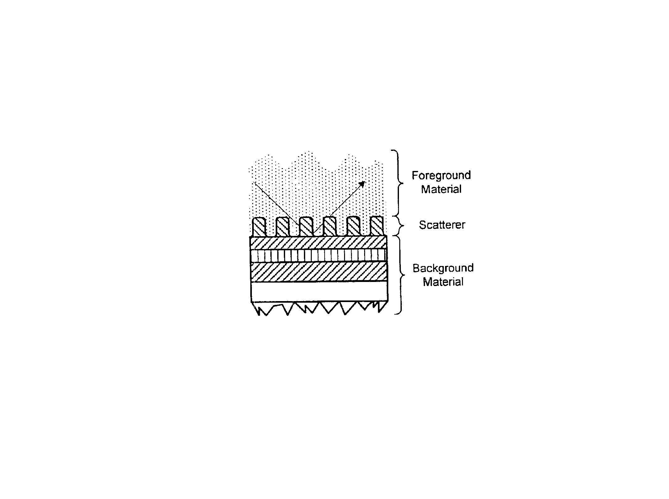
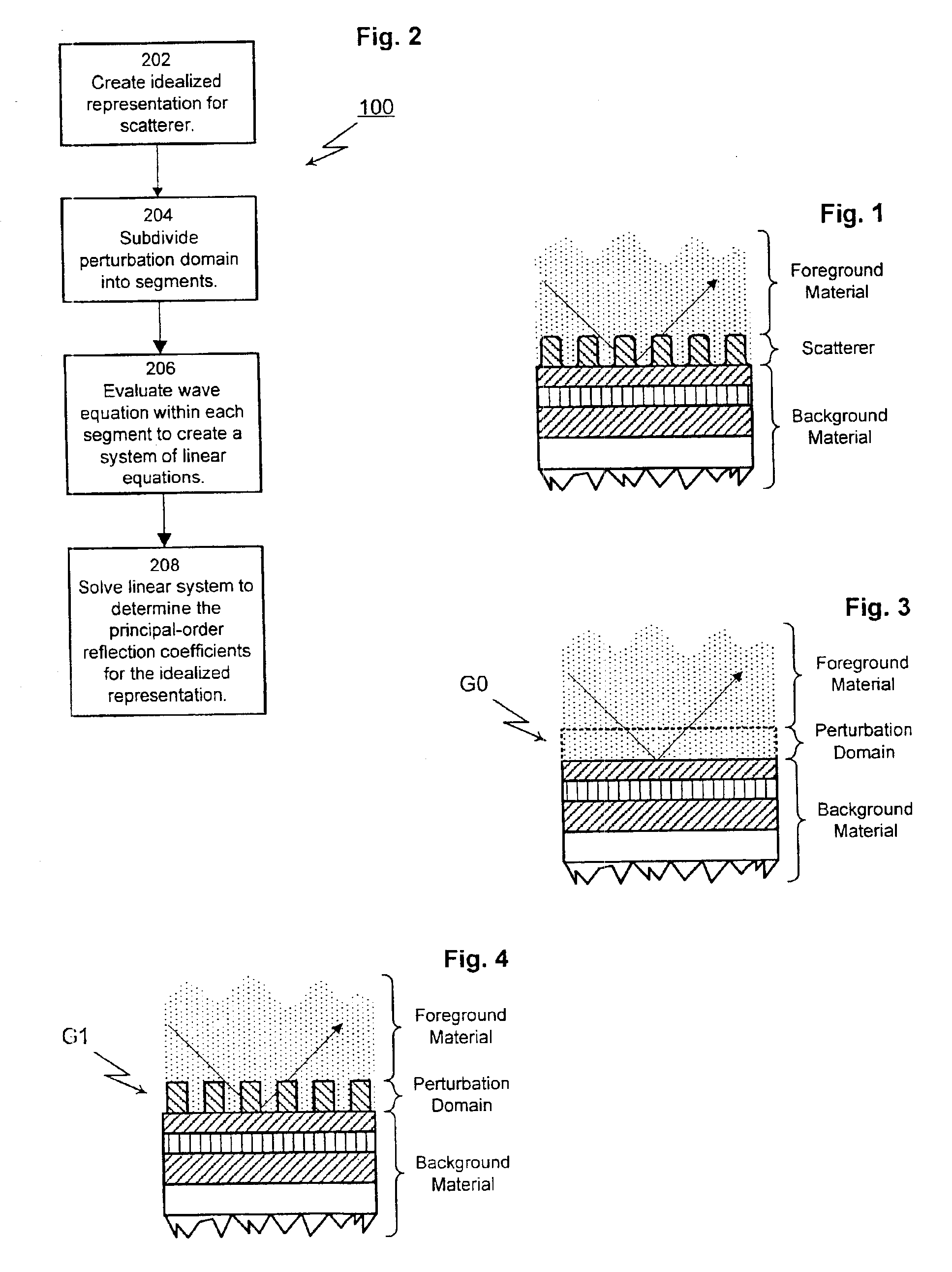
The present invention provides a method for modeling optical diffraction. The modeling method is intended to be used in combination with a wide range of subjects including semi-conductor wafers and thin films. As shown in FIG. 1, the cross section for a generic subject reveals a scatterer sandwiched between a foreground material and a background material. The scatterer is a periodic or isolated structure and may be two or three-dimensional. For semi-conductor wafers, single lines are typical examples of two-dimensional isolated scatterers. Parallel groups of lines evenly spaced are a common example of two-dimensional periodic scatterers. Single vias are an example of isolated three-dimensional scatterers. In groups, vias can be an example of periodic three-dimensional scatterer.

The background material includes each of the layers situated below the scatterer. For the case of semi-conductor wafers, the background material would typically be a multilayer dielectric film. The fo...


PUM


Abstract

A method for modeling optical scattering includes an initial step of defining a zero-th order structure (an idealized representation) for a subject including a perturbation domain and a background material. A Green's function and a zero-th order wave function are obtained for the zero-th order structure using rigorous coupled wave analysis (RCWA). A Lippmann-Schwinger equation is constructed including the Green's function, zero-th order wave function and a perturbation function. The Lippmann-Schwinger equation is then evaluated over a selected set of mesh points within the perturbation domain. The resulting linear equations are solved to compute one or more reflection coefficients for the subject.

Description

TECHNICAL FIELDThe subject invention relates to a technique for determining the scattering response of a periodic structure using a Green's function approach in combination with rigorous coupled wave analysis.BACKGROUND OF THE INVENTIONOver the past several years, there has been considerable interest in using optical scatterometry (i.e., optical diffraction) to perform critical dimension (CD) measurements of the lines and structures included in integrated circuits. Optical scatterometry has been used to analyze periodic two-dimensional structures (e.g., line gratings) as well as three-dimensional structures (e.g., patterns of vias or mesas). Scatterometry is also used to perform overlay registration measurements. Overlay measurements attempt to measure the degree of alignment between successive lithographic mask layers.Various optical techniques have been used to perform optical scatterometry. These techniques include broadband scatterometry (U.S. Pat. Nos. 5,607,800; 5,867,276 and ...

Claims


Application Information

Patent Timeline
IPC IPC(8): G01B11/00G01N31/00G01N21/47
CPCG01N21/4788
Inventor CHANG, YIA CHUNGCHU, HANYOUOPSAL, JON
Owner THERMA WAVE INC
Why Eureka
Try Eureka