Fluidic actuator

a technology of hydraulic actuators and actuators, which is applied in the direction of flexible wall reciprocating engines, reciprocating piston engines, positive displacement engines, etc., can solve the problems of actuators that have been subject to certain practical problems, their use, and can have a relatively long stroke, etc., to achieve low cost, long service life, and low friction

a technology of hydraulic actuators and actuators, which is applied in the direction of flexible wall reciprocating engines, reciprocating piston engines, positive displacement engines, etc., can solve the problems of actuators that have been subject to certain practical problems, their use, and can have a relatively long stroke, etc., to achieve low cost, long service life, and low friction

US6868773B2Active Publication Date: 2005-03-22ELECTRO CAM CORP

Image

  • Fluidic actuator
  • Fluidic actuator
  • Fluidic actuator

Examples


Embodiment Construction

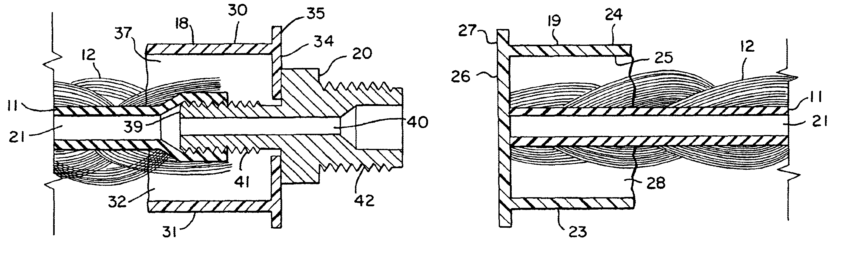
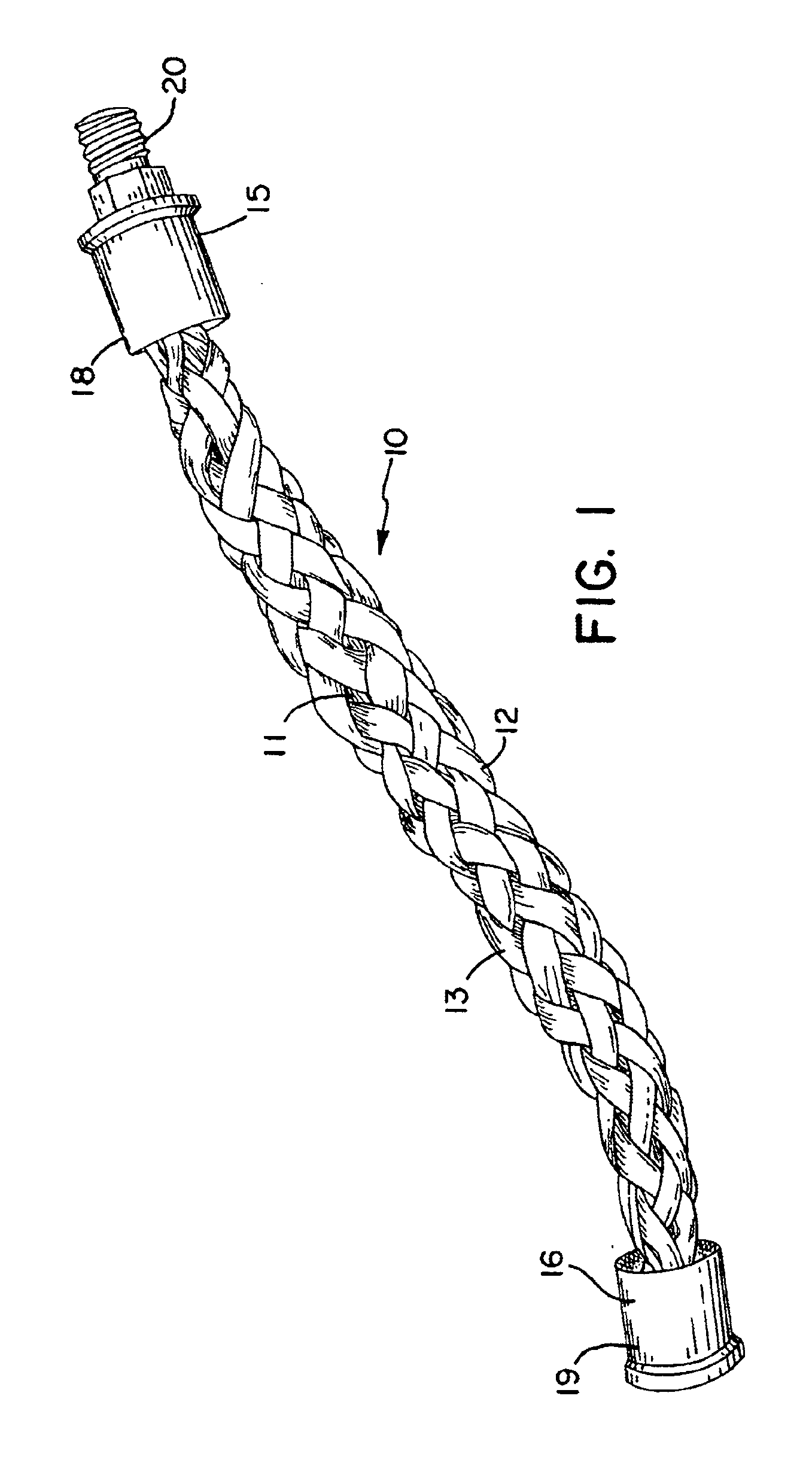
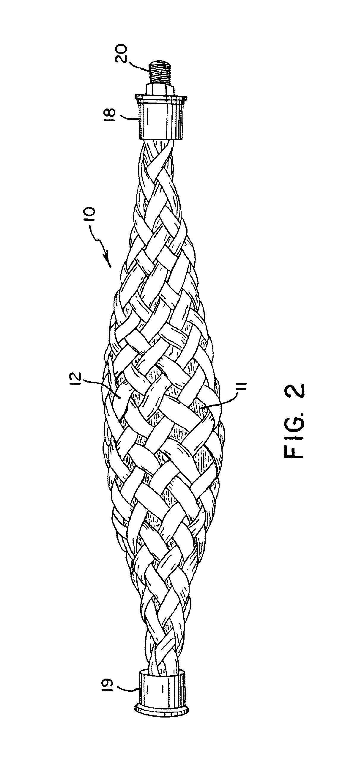
With reference to the drawings, a fluidic actuator in accordance with the invention is shown generally at 10 in FIG. 1 in its uncontracted or relaxed configuration. The actuator 10 has an elastic tube 11 (e.g., surgical tubing) which is surrounded by a sheath 12 formed of braided fibers 13. A thin-walled tube may be preferred for some purposes, and relatively thick walled tubes (e.g., ½ inch inside diameter / 1½ inch outside diameter) of elastics such as gum rubber may be preferable for other applications. The central tube is largely obscured in FIG. 1 by the outer sheath 12 and is more clearly illustrated in the cross-sectional views of FIGS. 3 and 4 taken at a first end 15 and a second end 16, respectively, of the actuator. End fittings 18 and 19 are attached to the ends of the tube 11 and the sheath 12 at the first end and second end, respectively, in a manner as discussed further below. The fitting 18 at the first end 15 includes a fluid coupling 20 by which a fluid supply line, e...


PUM


Abstract

A fluidic actuator includes a central elastic tube with an interior bore and a surrounding sheath formed of braided fibers. End fittings are attached to the tube and sheath at first and second ends thereof and include a cap with a hollow cavity into which an end section of the tube and sheath are inserted and embedded in a hardened adhesive. The hardened adhesive seals off the ends of the tube and strongly bonds the fibers of the sheath to the end caps to provide strong mechanical connections. A fluid coupling may extend through one of the end caps to connection to an end of the tube, with an interior bore in the coupling in communication with the bore in the tube to allow fluid under pressure to be supplied to the interior of the tube. A liquid lubricant may be held in the fibers of the sheath to provide lubrication between the elastic tube and the fibers of the sheath to reduce wear and abrasion of the tube and extend the service life of the actuator.

Description

FIELD OF THE INVENTIONThis invention pertains generally to the field of pneumatic and hydraulic actuators and particularly to contractile actuators, sometimes referred to as artificial muscle.BACKGROUND OF THE INVENTIONVarious types of fluidic actuators are utilized for converting pressurized fluids such as air or hydraulic fluid to mechanical motion. These actuators include the common piston-cylinder drive in which a piston slides within the chamber of a cylinder and is driven by a differential in fluid pressure across the piston, as in the very common commercially available air cylinder drives and hydraulic rams. Such actuators can have a relatively long stroke but are limited in applied force to the fluid pressure across the piston times the surface area of the piston. Another type of fluidic actuator simulates the action of natural muscle contraction. An elastic tube or bladder is surrounded by a sleeve or sheath of relatively inelastic material, typically braided fibers, and th...

Claims


Application Information

Patent Timeline
22 Mar 2005
Publication
US6868773B2
IPC
F15B15/00; F15B15/10
CPC
F15B15/103
Inventors
DAVIS, DONALD L.; CARLSON, JEFFREY A.