Bubble cap assembly

a bubble cap and assembly technology, applied in the direction of combustion types, lighting and heating apparatus, furnaces, etc., can solve the problem that the bubble cap cannot be welded to the stainless steel stem, and achieve the effect of reducing the overall cost of capital plus maintenan

Inactive Publication Date: 2005-03-22
THE BABCOCK & WILCOX CO +1
View PDF14 Cites 11 Cited by
  • Summary
  • Abstract
  • Description
  • Claims
  • Application Information

AI Technical Summary

Benefits of technology

Ceramics can withstand typical CFB furnace temperatures. In addition, ceramics are much more wear resistant than stainless steel and yet the cost of a ceramic bubble cap is comparable to that of the stainless steel one. Therefore, making bubble caps of ceramics may reduce their overall (capital plus maintenance) cost. However, a ceramic bubble cap cannot be welded to a stainless steel stem, which is the preferred method of assembly when both elements are made of stainless steel. Further, ceramic and steel materials have different coefficients of thermal expansion, stainless steel typically having a higher coefficient of thermal expansion than that of ceramic materials, precluding the use of a threaded approach for assembling the two types of materials together.

Problems solved by technology

However, a ceramic bubble cap cannot be welded to a stainless steel stem, which is the preferred method of assembly when both elements are made of stainless steel.

Method used


Image

  • Bubble cap assembly
  • Bubble cap assembly
  • Bubble cap assembly

Examples


Embodiment Construction

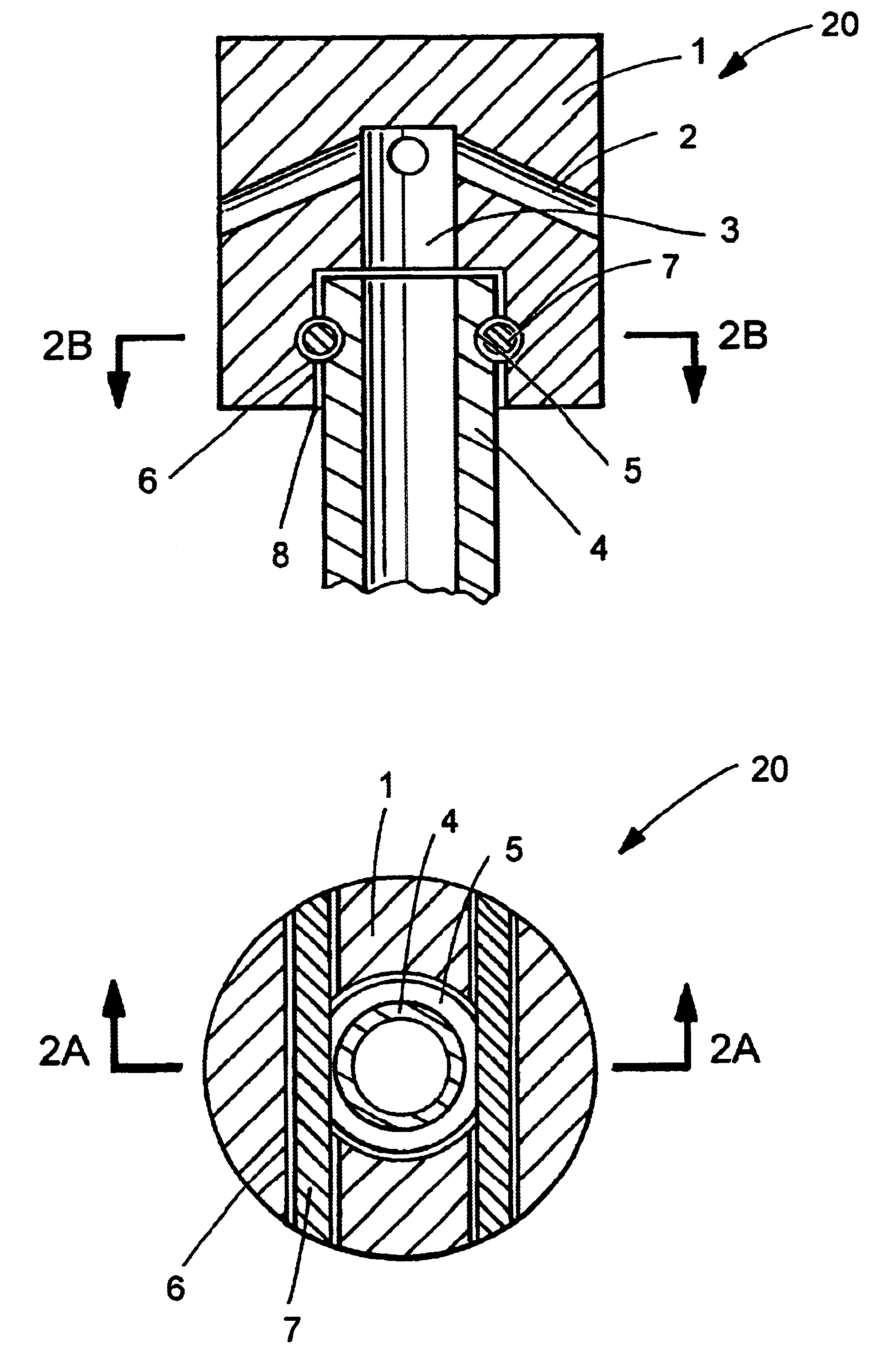
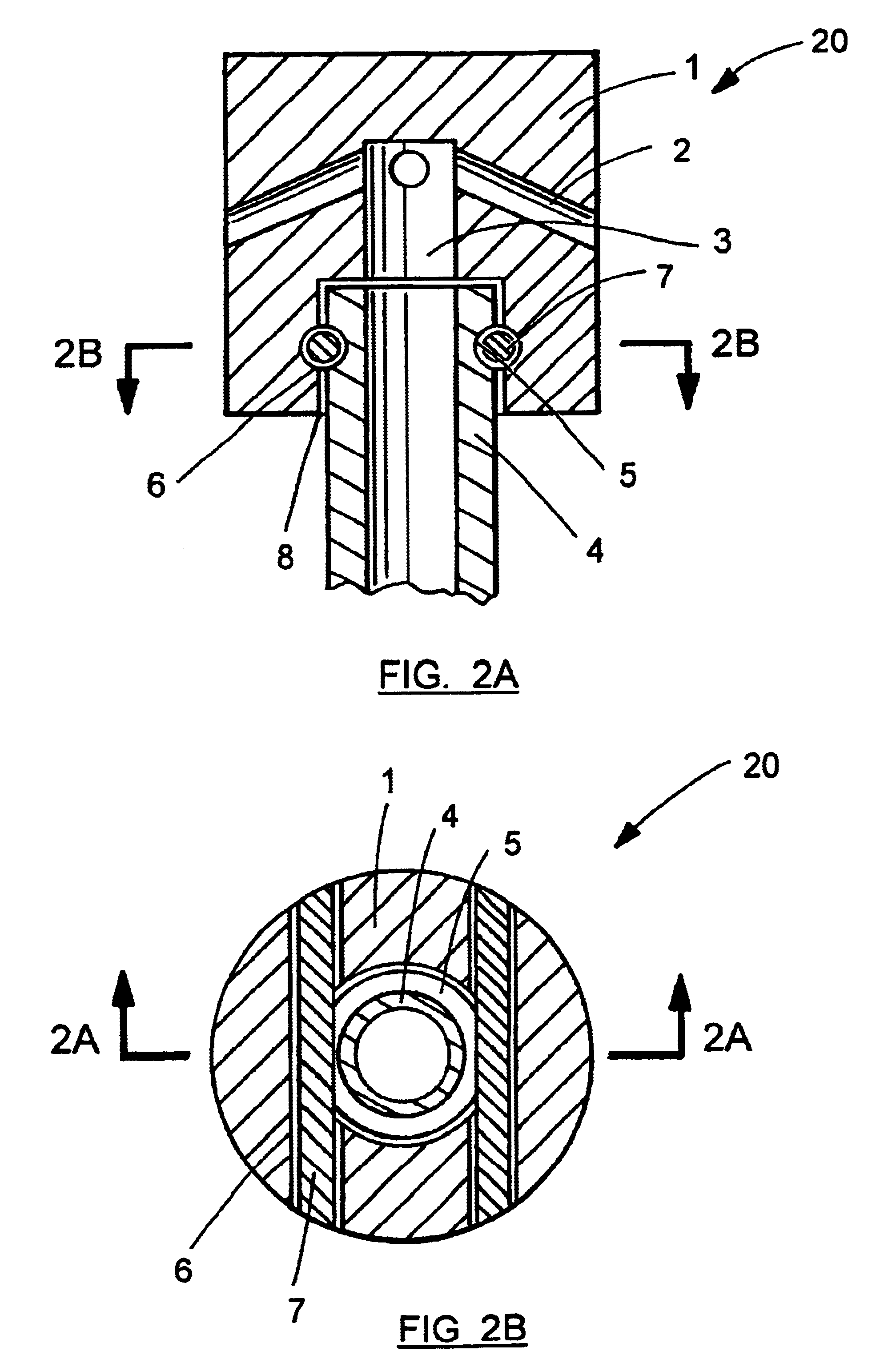
In the several drawings comprising the present disclosure, like reference numerals designate the same or functionally similar elements throughout the drawings. A preferred embodiment of the bubble cap assembly according to the present invention and generally designated 20, is shown in FIGS. 2A and 2B. The bubble cap assembly 20 is comprised of a ceramic bubble cap 1 which contains several outlet holes 2 connected through a central air passage 3 to a stainless steel stem 4. One end of the stem 4 is inserted into the bubble cap 1, while the other end (not shown) is connected to a source of fluidizing medium, such as air or other gaseous fluids. The end of the stem 4 which is inserted into the bubble cap 1 is provided with a circular groove 5 on its outer surface. In this embodiment, the bubble cap 1 has two insertion holes 6, their axes being substantially perpendicular to the axis of the stem 4, but this orientation is not critical to the practice of the invention. Each insertion hol...


PUM


Abstract

A bubble cap assembly for use in fluidized bed boilers, furnaces, or reactors, has a bubble cap, a stem, and at least one pin. One end of the stem is inserted into the bubble cap. The bubble cap has outlet holes for delivering a fluidizing medium, typically into a bed of granulated material, but which prevent backsifting of the granulated material into the bubble cap. The bubble cap also has at least one insertion hole, through which a pin may be inserted. When the pin is inserted through the bubble cap insertion hole, it also occupies a groove or indentation on the stem thereby preventing separation or disassembly of the bubble cap and stem combination. An elastic gasket may be provided between the bubble cap and stem to form a fluid tight connection.

Description

FIELD AND BACKGROUND OF THE INVENTIONThe present invention relates generally to the field of fuel burning for power and steam generation and, in particular, to a new and useful bubble cap assembly for supplying a fluidizing medium to a fluidized bed.Circulating Fluid Bed (CFB) technology has found popularity as an attractive way to burn solid fuels to provide steam and power. This popularity is evident both domestically and abroad. In a combustion setting, CFB technology provides good combustion efficiency with low emissions and provides fuel flexibility because it is well suited for burning a wide range of solid fuels such as coal, waste coal, anthracite, lignite, petroleum coke, and agricultural waste. Consequently, it has emerged as an environmentally acceptable technology for utility and industrial applications.In a circulating fluidized-bed furnace or boiler, the bed material, which normally comprises crushed fuel, limestone and ash, is suspended in the stream of air at about 6...

Claims


Application Information

Patent Timeline
Patent Type & Authority Patents(United States)
IPC IPC(8): F02M29/00F02M29/04F23G5/00F23C10/18F23C10/20F23C10/00F23G5/30
CPCF23C10/20
Inventor MARYAMCHIK, MIKHAILANDERSON, GARY L.HAHN, JEFFREY J.COLLINS, III, EDWIN L.WALKER, DAVID J.BOLEBRUCH, JEFFREY J.
Owner THE BABCOCK & WILCOX CO
Why Eureka
Try Eureka