Method and apparatus for directionally solidified casting

Inactive Publication Date: 2005-03-22
MITSUBISHI HEAVY IND LTD
View PDF11 Cites 10 Cited by
  • Summary
  • Abstract
  • Description
  • Claims
  • Application Information

AI Technical Summary

Benefits of technology

As described above, according to the present invention, it is possible to provide the directional solidification casting apparatus and the directional solidification casting method capable of heightening a cooling effect when molten material is directionally solidified. The productivity of a directionally solidified casting can be improved by the directional solidification casting apparatus and method de

Problems solved by technology

However, in the directional solidification achieved by the conventional method and apparatus, there is a case where a structural defect called “anisotropic crystals” or a structural defect called “freckle” occurs if the shape of a part to be cast is complex, or if a method by which a plurality of products are produced by carrying out a one-time casting process is employed.
Thi

Method used


Image

  • Method and apparatus for directionally solidified casting
  • Method and apparatus for directionally solidified casting
  • Method and apparatus for directionally solidified casting

Examples


first embodiment

The present invention will hereinafter be described in detail based on the first embodiment shown in the attached drawings.

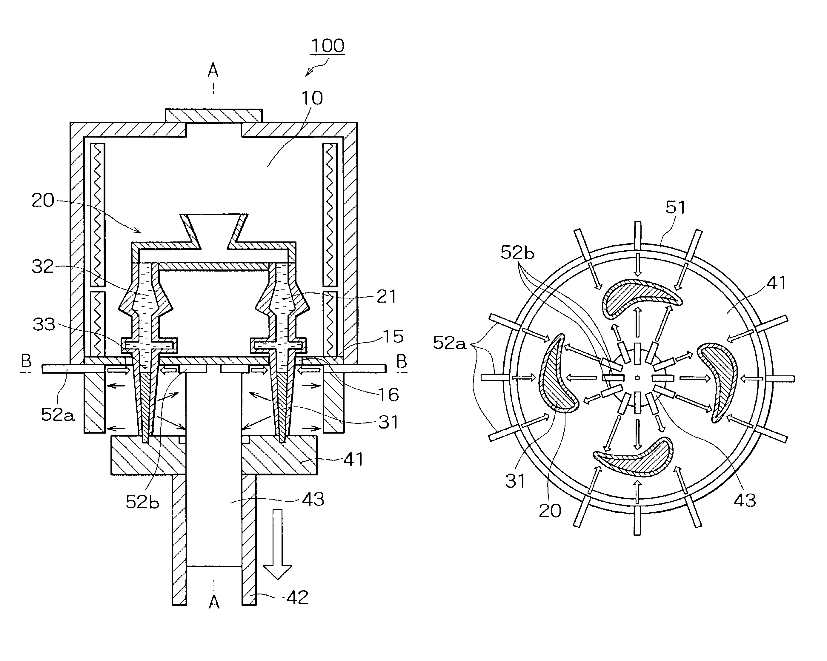
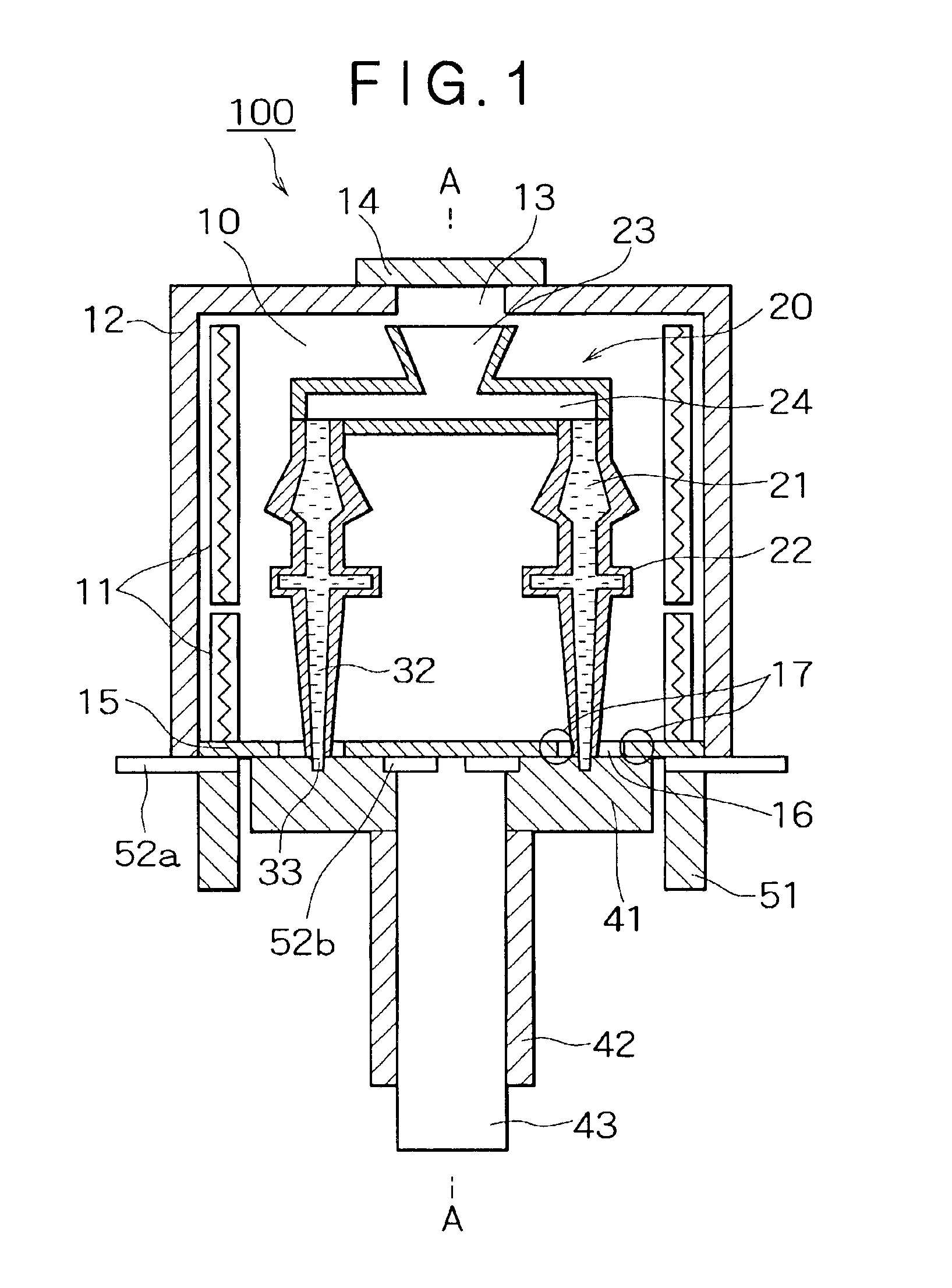
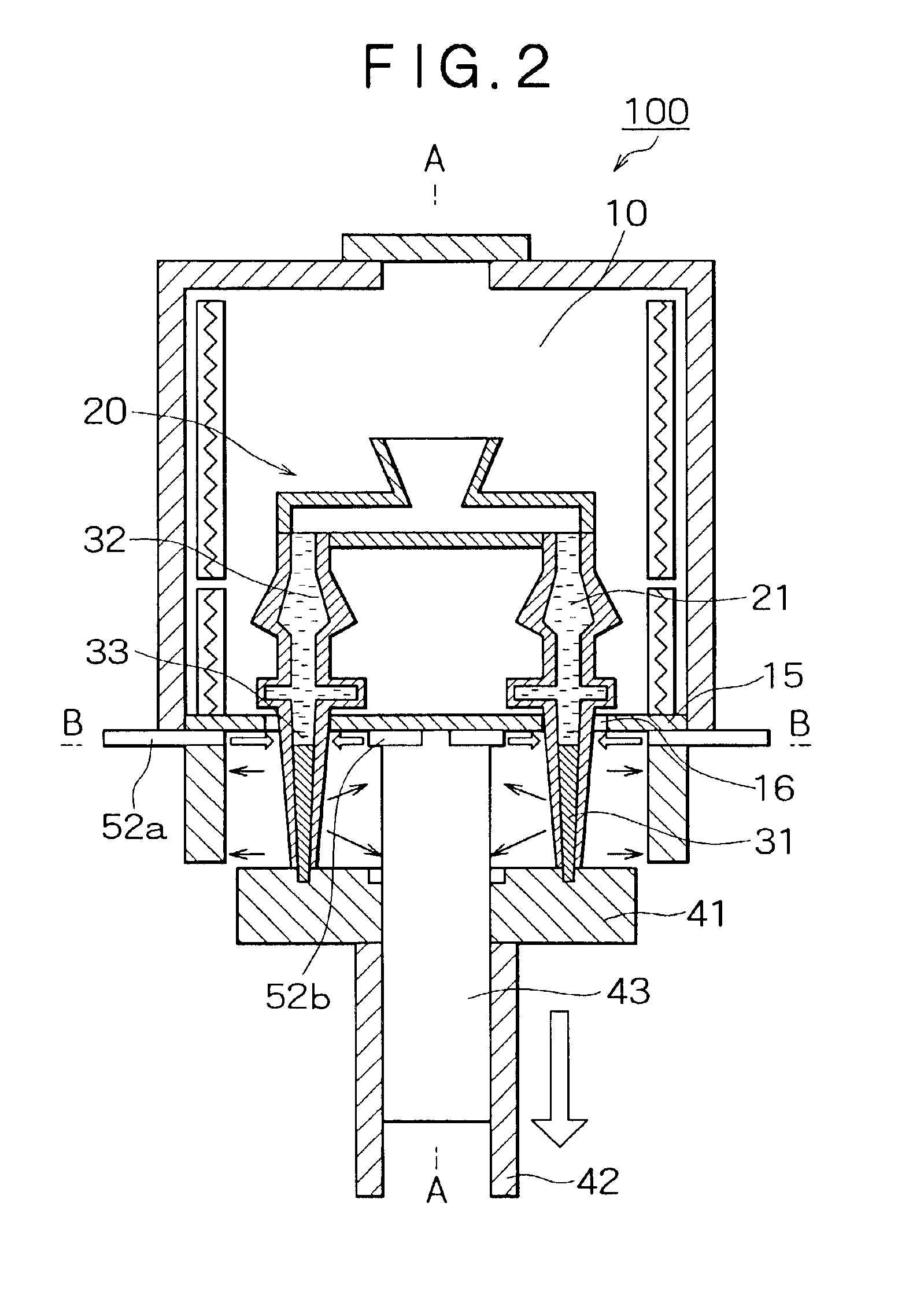
FIG. 1 shows the structure of a directional solidification casting apparatus 100 in the first embodiment. Herein, a description will be given of a case where a blade, such as that of a turbine, is cast by directional solidification. A plane cross-sectional view of the directional solidification casting apparatus 100 is shown in FIG. 3 when cut along line B—B in a cooling process described later with reference to FIG. 2. In other words, in the directional solidification casting apparatus 100 described in the first embodiment, a plurality of blades (four blades in the figure) can be cast as shown in FIG. 3.

As shown in FIG. 1, a heating chamber 10 of the directional solidification casting apparatus 100 is surrounded by a cover 12, excluding its bottom face. A heater 11 is disposed on the inner side face of the cover 12 of the heating chamber 10. An opening 13 is fo...

second embodiment

A second embodiment will hereinafter be described with reference to FIG. 4. FIG. 4 is a plane cross-sectional view of the directional solidification casting apparatus 100 in the second embodiment. The plane cross-sectional view of FIG. 4 shows a state where the directional solidification casting apparatus 100 described in the first embodiment is cut along the line B—B like the plane cross-sectional view of FIG. 3. Except for the directions of the gas nozzles 52a and 52b, the directional solidification casting apparatus 100 in the second embodiment is structured in the same way so as in the directional solidification casting apparatus 100 described in the first embodiment, and therefore a description thereof is omitted.

As shown in FIG. 4, the mold 20 is disposed in a predetermined area in such a way so as to surround the heat sink 43. The water-cooled ring 51 is disposed at the side of the outer periphery of the mold 20, and, together with the heat sink 43 disposed at the inner perip...

third embodiment

A third embodiment will hereinafter be described with reference to FIG. 5.

FIG. 5 shows the structure of the directional solidification casting apparatus 100 in the third embodiment. This directional solidification casting apparatus 100 has almost the same structure as those in the first and second embodiments. In this directional solidification casting apparatus 100, the mold 20 placed on the cooling plate 41 is drawn out from the heating chamber 10 by lowering the driving rod 42 along the axial line A—A. Instead of the gas nozzles 52a and 52b described in the first and second embodiments, a perforated pipe 53a and a perforated pipe 53b for cooling the mold 20 are provided. The water-cooled ring 51 is disposed at the lower part of the heating chamber 10.

FIG. 6 is a plane cross-sectional view of the directional solidification casting apparatus 100 in the third embodiment. The plane cross-sectional view of FIG. 6 shows a state where the directional solidification casting apparatus 100...


PUM

PropertyMeasurementUnit
Radiant heataaaaaaaaaa
Melting pointaaaaaaaaaa

Abstract

Provided is a directional solidification casting apparatus capable of heightening a cooling effect when molten material poured in a mold is directionally solidified. A mold (20) disposed around a predetermined area is drawn out from a heating chamber (10) heated above a melting temperature of metals for producing a casting (31), and molten metals (32) held in a cavity (21) of the mold (20) are directionally solidified. The directional solidification casting apparatus (100) comprises a driving rod (42) by which the mold (20) is drawn out from the heating chamber (10), a gas nozzle (52b) through which a cooling gas is jetted from inside a predetermined area where the mold (20) is disposed so as to rapidly cool the mold (20), and a gas nozzle (52a) through which a cooling gas is jetted from outside the predetermined area where the mold (20) is disposed so as to rapidly cool the mold (20). A baffle (15) that does not move even when the driving rod (42) moves up and down is additionally provided. The baffle (15) blocks radiant heat emitted from the heating chamber (10).

Description

BACKGROUND OF THE INVENTION1. Field of the InventionThis invention relates to a method for producing a unidirectionally solidified casting and an apparatus for producing the same, and, more particularly, to a directional solidification casting method for casting a stationary blade, a rotor blade or the like such as that of a gas turbine, and an apparatus for casting the same.2. Description of the Related ArtConventionally, a Bridgeman method has been used to produce a casting that has a part onto which a great thermal and mechanical load is imposed. A stationary blade or a rotor blade of a gas turbine formed intricately can be mentioned as one example of such a part. A casting directionally solidified according to the Bridgeman method exhibits single crystals or columnar crystals oriented in advantageous directions.A description will be given of a conventional method for producing a directionally solidified casting with reference to FIG. 8. A directionally solidified casting has bee...

Claims


Application Information

Patent Timeline
IPC IPC(8): B22D27/04F02C7/00
CPCB22D27/045
Inventor SHIMOHATA, SACHIOOHTANI, YUICHIOHIRA, TATSUYAOKADA, IKUO
Owner MITSUBISHI HEAVY IND LTD
Why Eureka
Try Eureka