Supercharge Your Innovation With Domain-Expert AI Agents!

Methods and devices for the manufacture of bristle products

a technology of bristle and products, applied in the field of methods and devices for the manufacture of bristle products, can solve problems such as adverse effects on process safety and product quality, and achieve the effects of enhancing process safety, reducing susceptibility to trouble, and increasing product quality

Inactive Publication Date: 2005-03-22
BRAUN GMBH
View PDF10 Cites 1 Cited by
  • Summary
  • Abstract
  • Description
  • Claims
  • Application Information

AI Technical Summary

Benefits of technology

Because clusters of bristles are conveyed actively by opposite pressure surfaces provided at both sides of the cluster of bristles, dead zones in which no continuous flow of bristles takes place are avoided. Effects known under the term “arching” or “bridging” generally will not occur because the bristles are fed actively from both sides. “Arching” or “bridging” is understood to mean an apparent interlocking of the bristle clusters, which impedes solid body flow. The pressure surfaces form a laterally bordering bristle track, between which the two sides of the bristle cluster abut by means of the bearing pressure formed by the pressure surfaces. In this way, a safe and steady conveyance of the bristles is achieved and, here, both pressure surfaces run synchronously at the same velocity.
Furthermore, active filament feed expedites the removal of interferences occurring in the filament bed, generally resulting in an increased product quality. This means that sections in the filament supply duct in which filaments have lost their upright orientation due to external influences are pushed out of the filament supply duct more quickly. This results in a reduced susceptibility to trouble and enhances process safety. In addition, it enables the filaments to be picked up symmetrically from the middle of the duct. To achieve this, it is preferred that the opposing conveying devices be arranged symmetrically at the duct. A higher constancy in the number of filaments flowing into the recesses of the picker segment on each operating cycle is also generally achieved.
Another advantageous effect is a reduced dependence upon the filament finish level. This means that the supply of bristle clusters is independent of the filament manufacturing process and the filament type while process safety is maintained at a consistently high level. This also enables processing of filaments proceeding at a very slow rate. This becomes apparent, for example, from the smooth processing of particularly fine filaments with a diameter less than, for instance, 0.12 mm, which corresponds to about 0.005 inch.
The device may be configured to be synchronized with a subsequent sequence of operations. In this case, the filaments on both sides of the conveying device are generally transported steadily and synchronously, thus avoiding relative displacements of the individual bristles with respect to each other.

Problems solved by technology

It is a disadvantage of the known methods and constructions of the known filament supply ducts that zones occur in which a continuous filament flow is not allowed to develop.
These zones, also referred to as dead zones, have an adverse effect on process safety and product quality.

Method used


Image

  • Methods and devices for the manufacture of bristle products
  • Methods and devices for the manufacture of bristle products
  • Methods and devices for the manufacture of bristle products

Examples


first embodiment

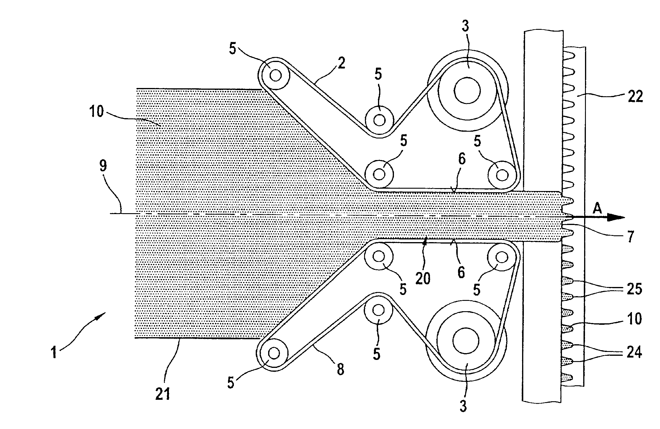
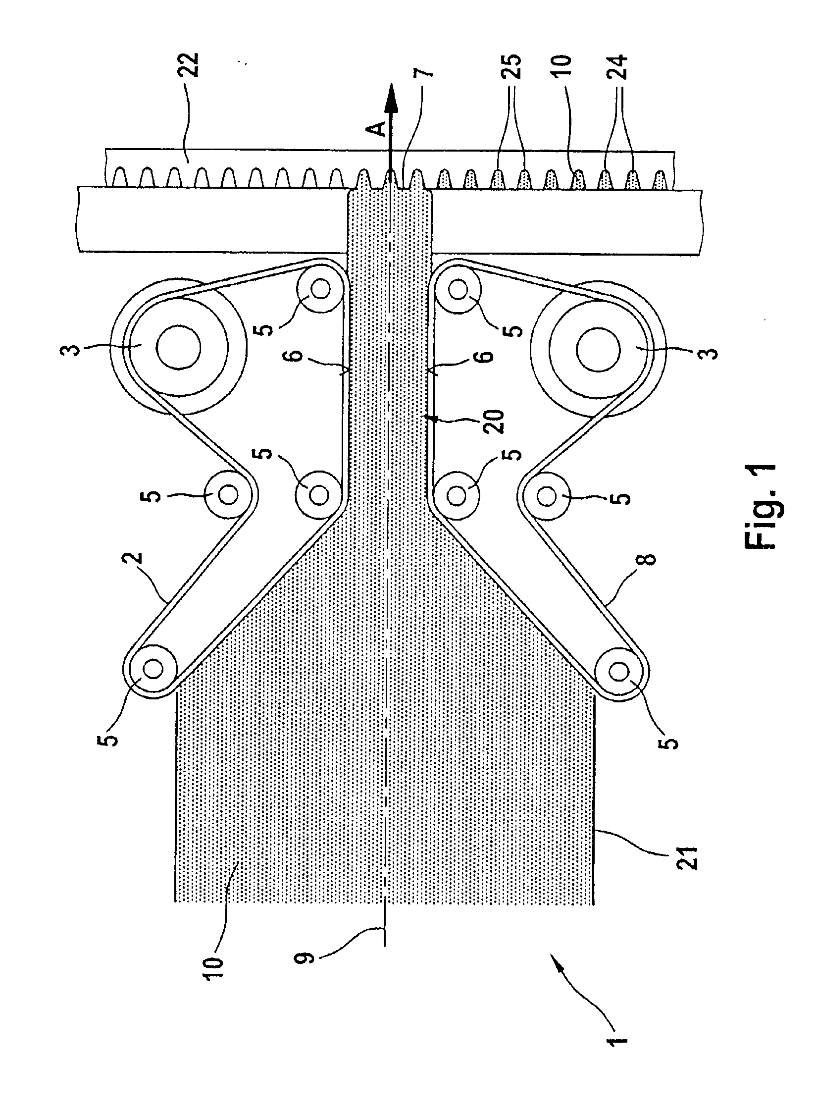
FIG. 1 shows in a schematic sectional view an active feed unit 1, i.e., a driven bristle conveying device, including an upper conveyor belt 2 and a lower conveyor belt 8, each constructed as a driven flat belt of elastomer plastic.

The upper conveyor belt 2 and the lower conveyor belt 8 are arranged in mirror symmetry about an axis of symmetry 9. The architecture of the conveyor belts 2, 8 is therefore described only once.

The symmetrical conveyor belts 2, 8 each include one drive wheel 3 and four deflection pulleys 5. The conveyor belt 2, 8 is wrapped around the deflection pulleys 5 in such fashion that a straight-line tensioned pressure surface 6 parallel to the axis of symmetry 9 is produced between the two deflection pulleys 5. Arranged in spaced relation to the pressure surface 6 and the line of symmetry 9 is the drive wheel 3 around which the conveyor belt 2, 8 is wrapped for nearly half the wheel circumference. Adjacent to the drive wheel 3 is another deflection pulley 5 which ...

second embodiment

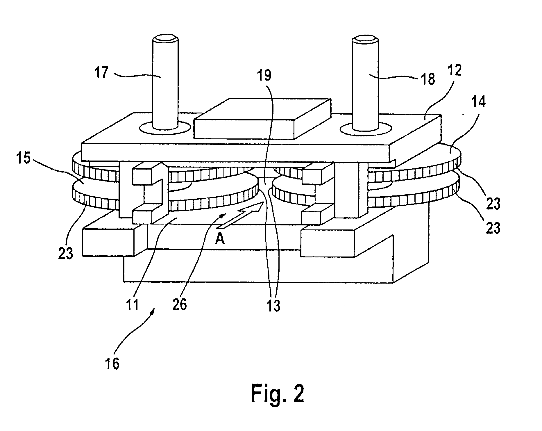
FIG. 2 shows a perspective view of an active feed unit 15. The feed unit 15 of this embodiment comprises a base plate 11 and a cover plate 12. The base plate 11 and the cover plate 12 are made from solid, machined metal. Rotatably arranged between the base plate 11 and the cover plate 12 are a right-hand gear 14 and a left-hand gear 15, each having grooves 23 into which the bristles 10 slide to be conveyed in the direction of arrow A. The two gears 14, 15 are driven by two synchronized drive shafts and are not in meshing engagement with each other, but rather, a gap 19 is provided between the right-hand gear 14 and the left-hand gear 15 through which precut lengths of upstanding bristles (not shown), also designated as filament clusters or strands, which are arranged loosely in a supply duct, are routed directly to a picker segment for picking up the tufts. The gears 14, 15 form the lateral boundaries for the gap 19 and serve as pressure surfaces 13, producing also in this area, sim...


PUM


Abstract

The invention is directed to a device for the manufacture of bristle products, in particular toothbrushes, with a feed unit for precut lengths of upstanding bristles arranged loosely in a supply duct, the bristles being routed directly to a picker segment picking up the bristles. The device includes a driven conveyor at the end of the supply duct close to the picker segment, or a further processing station.

Description

CROSS-REFERENCE TO RELATED APPLICATIONThis application claims the benefit of German application Ser. No. 101 43 674.2 filed Sep. 6, 2001.TECHNICAL FIELDThis invention relates to methods and devices for the manufacture of bristle products, such as toothbrushes.BACKGROUNDDevices for the manufacture of bristle products, such as toothbrushes, are well known.Thus, for example, U.S. Pat. No. 4,360,236 describes a double fiber magazine for a brush manufacturing machine, comprising two magazines immovably connected to each other. The magazines are located opposite a picker or bundle plucker. According to this disclosure, each magazine is provided with a separating device and pressing components for pressing the fibers towards the bundle plucker. Moreover, provision is made for a device which alternately loads the fibers beyond the reach of the bundle plucker into one of the two fiber magazines. The double fiber magazine described in U.S. Pat. No. 4,360,236 finds application, for example, in...

Claims


Application Information

Patent Timeline
Patent Type & Authority Patents(United States)
IPC IPC(8): A46D3/08A46D1/00A46D1/08A46D3/00
CPCA46D3/082A46D1/08
Inventor STEIN, BERNDFLOOD, BRYAN
Owner BRAUN GMBH
Features
  • R&D
  • Intellectual Property
  • Life Sciences
  • Materials
  • Tech Scout
  • Unparalleled Data Quality
  • Higher Quality Content
  • 60% Fewer Hallucinations
Learn More