
Temperature compensation system for regulating flow through tubing in a pump

a temperature compensation and pump technology, applied in the direction of positive displacement liquid engines, liquid fuel engines, instruments, etc., to achieve the effect of convenient operation, convenient setting up, and convenient operation

Inactive Publication Date: 2005-03-22
ICU MEDICAL INC
View PDF4 Cites 52 Cited by
  • Summary
  • Abstract
  • Description
  • Claims
  • Application Information

AI Technical Summary

Benefits of technology

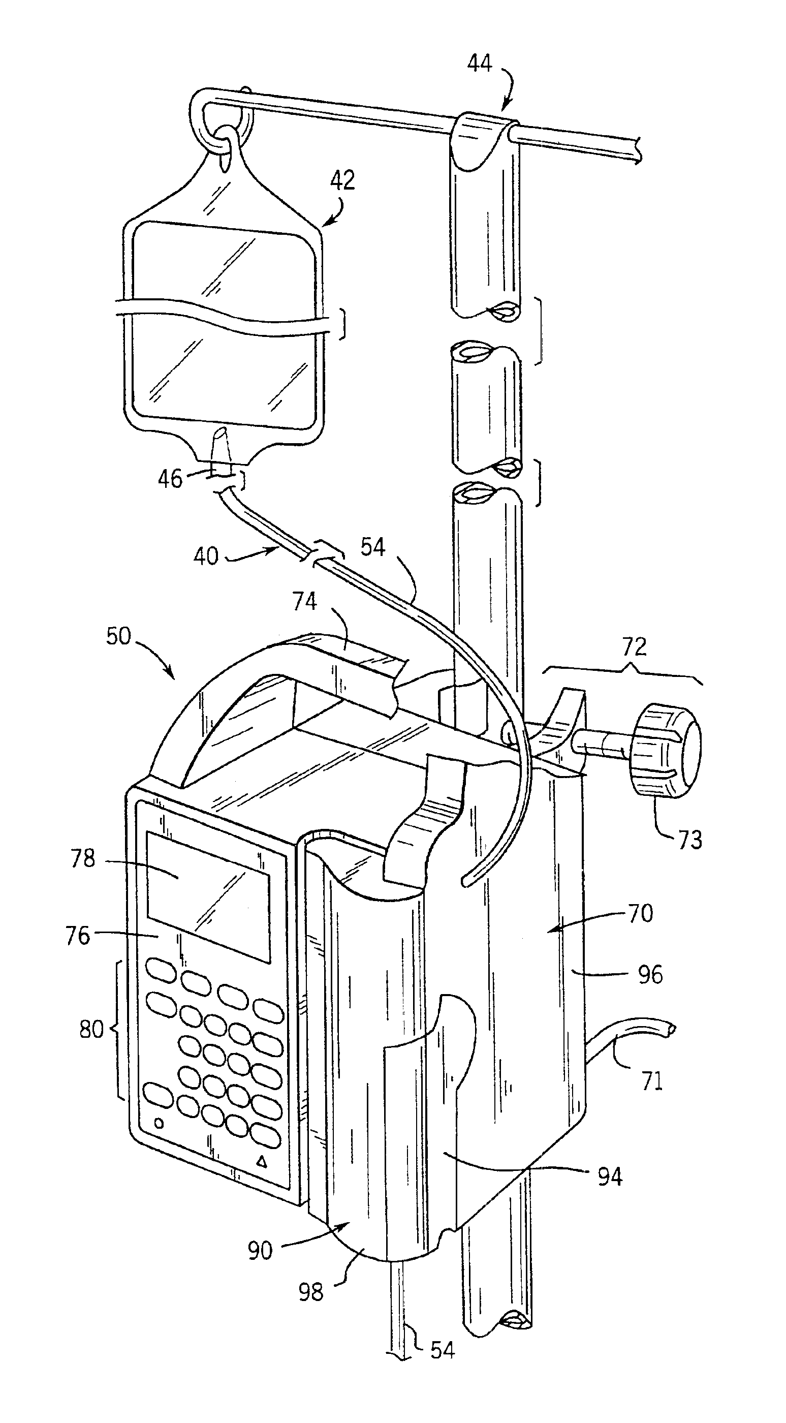
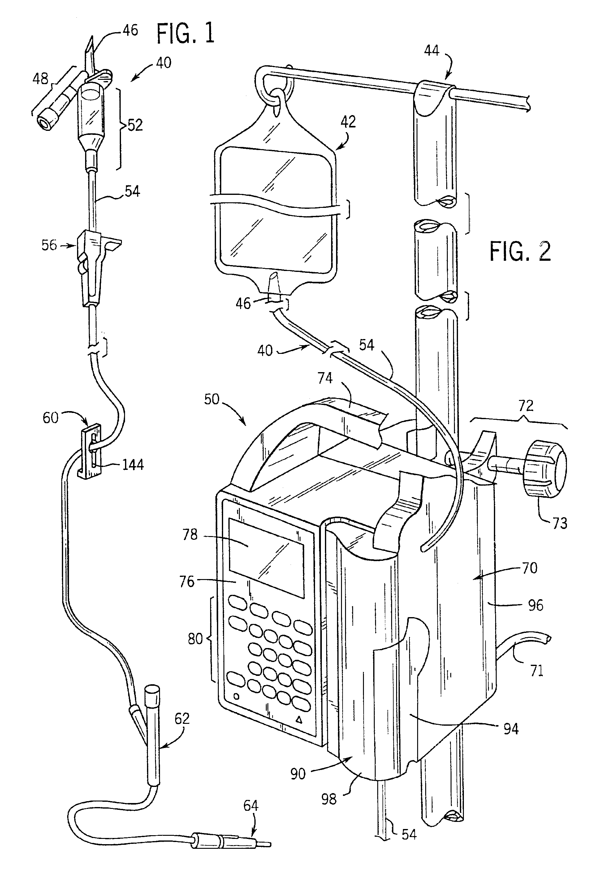
The present invention provides an improved system which can accommodate designs that have the above-discussed benefits and features. The system is convenient to use and is cost-effective with respect to its manufacture and operation. The system is especially suitable for use in a peristaltic pump. However, the system is applicable to other types of pumps wherein fluid is pumped through tubing and the fluid temperature cannot be directly sensed.
The system is easily operated and can be used with a wide variety of standard administration sets and fluid containers. The system is designed to meet the growing demand for hospital-wide standardization, as well as alternate-site, in-home healthcare standardization.
The improved system of the present invention accommodates safe delivery of fluids to a patient. The system is convenient to operate and is easy to set up.

Problems solved by technology

However, the system is applicable to other types of pumps wherein fluid is pumped through tubing and the fluid temperature cannot be directly sensed.

Method used


Image

  • Temperature compensation system for regulating flow through tubing in a pump
  • Temperature compensation system for regulating flow through tubing in a pump
  • Temperature compensation system for regulating flow through tubing in a pump

Examples


Embodiment Construction

While this invention is susceptible of embodiment in many different forms, this specification and the accompanying drawings disclose only one specific form as an example of the invention. The invention is not intended to be limited to the embodiment so described, however. The scope of the invention is pointed out in the appended claims.

For ease of description, a pump incorporating features of this invention is described in one normal (upright) orientation, and terms such as upper, lower, horizontal, etc., are used with reference to this orientation. It will be understood, however, that the pump of this invention may be stored, transported, and sold in an orientation other than the orientation described.

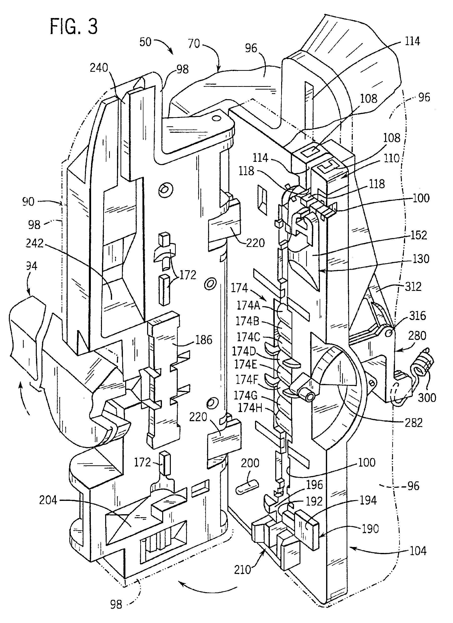
Figures illustrating the pump show some mechanical elements that are known and that will be recognized by one skilled in the art. The detailed descriptions of such elements are not necessary to an understanding of the invention, and accordingly, are herein presented only to the degree...


PUM


Abstract

A peristaltic pump is provided with a housing, a pump head in the housing, and a receiving path defined along a housing and pump head for receiving tubing. Two spaced-apart temperature sensors are provided. One temperature sensor is located adjacent the tubing in a heat conduction path along which heat flows between the sensor and the tubing. The other sensor is located outside of the heat conduction path for sensing ambient temperature. The pump operating speed is adjusted as a function of the sensed temperatures. This accommodates the temperature-dependent rate of recovery of the tubing from its peristaltically deformed configuration to its original configuration.

Description

STATEMENT REGARDING FEDERALLY SPONSORED RESEARCH OR DEVELOPMENTNot applicable.REFERENCE TO A MICROFICHE APPENDIXNot applicable.TECHNICAL FIELDThis invention relates to a liquid delivery system and is especially suitable for use as part of an infusion pump system designed to deliver parenteral and enteral fluids, as well as whole blood or red blood cell components, using a wide variety of standard intravenous administration sets and fluid containers.BACKGROUND OF THE INVENTION AND TECHNICAL PROBLEMS POSED BY THE PRIOR ARTOne conventional type of infusion pump system employs a peristaltic pump in conjunction with an intravenous administration set. The set consists of flexible thermoplastic tubing through which fluid flows from a suspended container, such as a flexible bag or rigid bottle, to a patient's indwelling vein access device, such as a needle or cannula inserted into the patient. A length of the administration set tubing between the fluid container and the patient is mounted i...

Claims


Application Information

Patent Timeline
IPC IPC(8): F04B49/20F04B43/00F04B43/08G05D7/06A61M1/36F04C5/00A61M5/00F04B43/12
CPCF04B43/08G05D7/0676F04B49/20F04B2205/09
Inventor BRIGGS, KENNETH D.PRYCE, DEAN C.SAMPSON, RUSSEL M.
Owner ICU MEDICAL INC
Learn More