
System and method of amplifier gain control by variable bias and degeneration

a variable gain and amplifier technology, applied in amplifiers with semiconductor devices/discharge tubes, amplifier control details, differential amplifiers, etc., can solve the problems of high power consumption, limited degeneration resistance range, and limited voltage headroom of typical low supply voltages

Inactive Publication Date: 2005-03-22
MALIKIE INNOVATIONS LTD
View PDF4 Cites 37 Cited by
  • Summary
  • Abstract
  • Description
  • Claims
  • Application Information

AI Technical Summary

Problems solved by technology

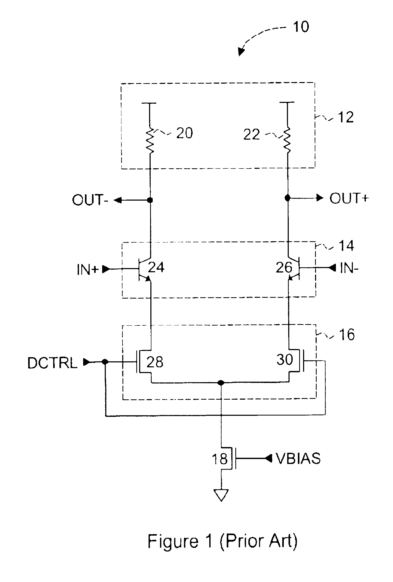
Hence, if the circuit is biased at a fixed tail current by transistor 18 via VBIAS, the range of degeneration resistance is severely limited by bias considerations.
A problem with this solution is that the large voltage drop across Rdegen cause voltage headroom limitations for the typical low supply voltages that are used in low power applications.
Since most VGA circuits operate normally at gain levels significantly lower than maximum gain, high power consumption results.
Thus, gain of the circuit can be controlled over a wide input signal dynamic range, but at the expense of linearity and / or power, making the VGA circuit 10 prior amplifier control techniques an unacceptable solution in low power / high linearity applications.

Method used


Image

  • System and method of amplifier gain control by variable bias and degeneration
  • System and method of amplifier gain control by variable bias and degeneration
  • System and method of amplifier gain control by variable bias and degeneration

Examples


Embodiment Construction

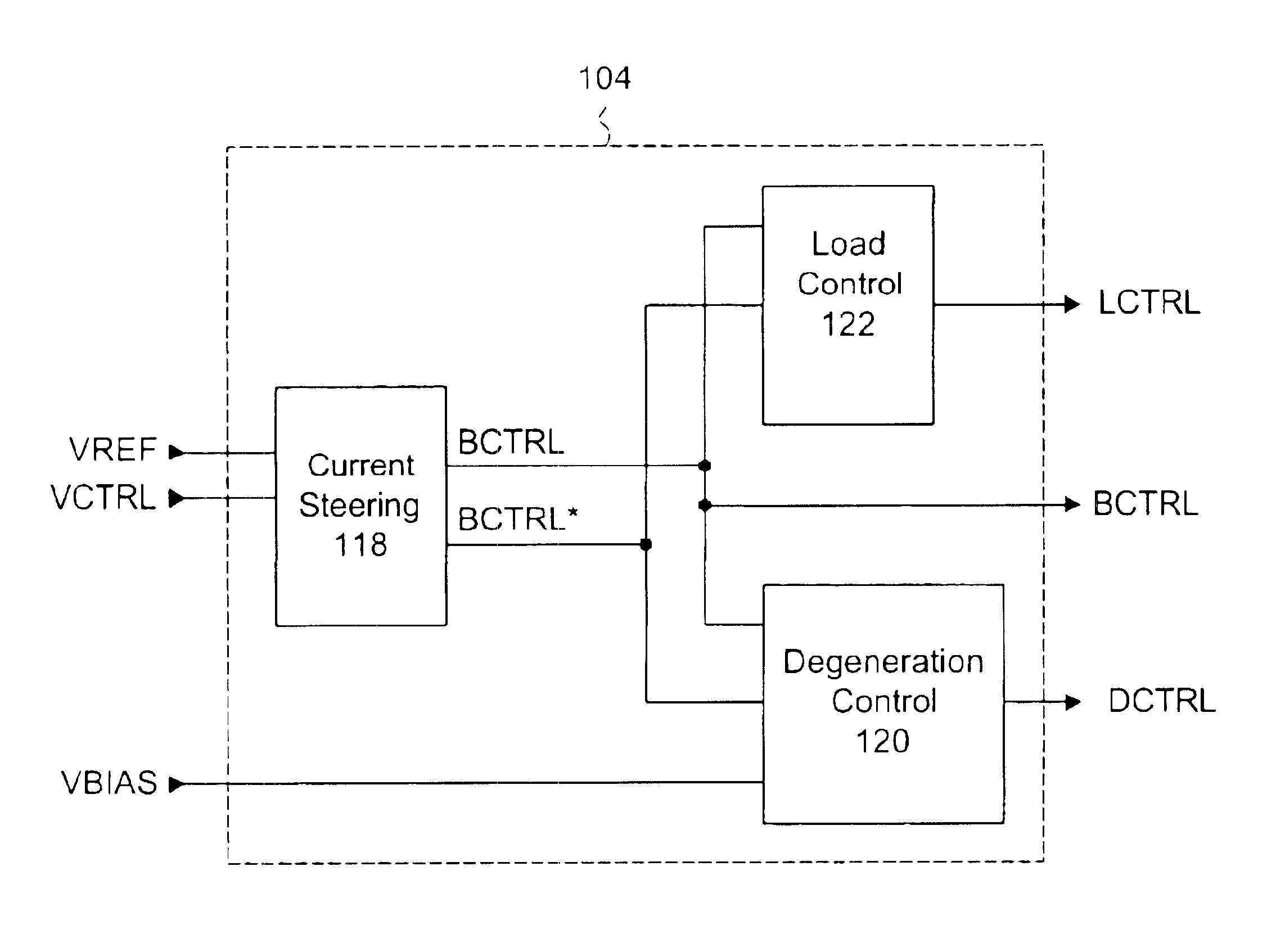
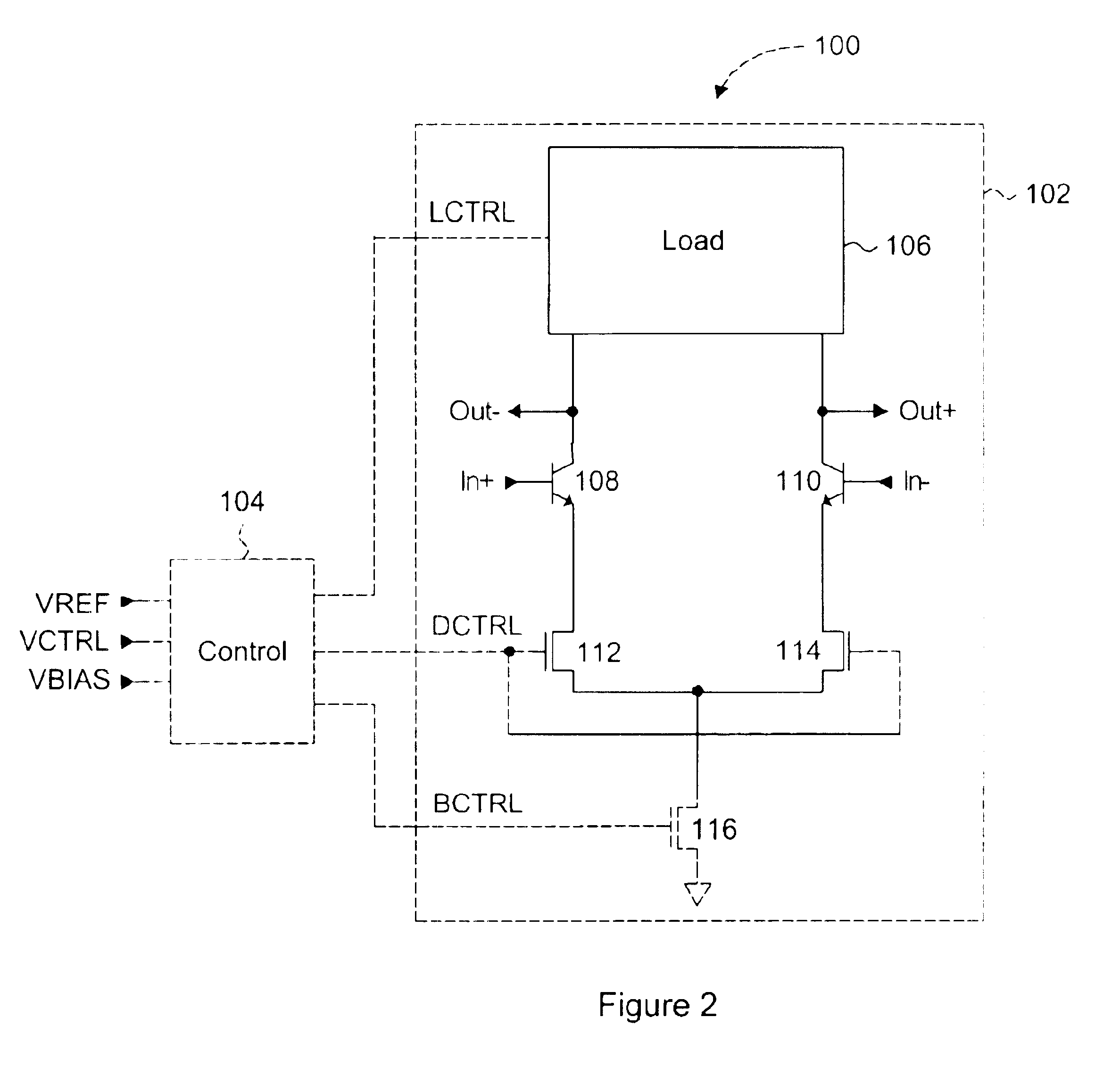
A gain control circuit that permits a variable gain amplifier circuit to operate with high input linearity and low power consumption is disclosed. The variable gain amplifier includes a standard differential bipolar transistor input circuit and a pair of degeneration transistors connected to a current source transistor. The gain control circuit provides a variable degeneration control voltage to vary the effective resistance of the degeneration transistors and a variable bias voltage to vary the current of the current source transistor. The input linearity of the variable gain amplifier is controlled independently of gain by adjusting the effective resistance and the current in an inverse relationship such that at maximum gain the current is at a maximum while the degeneration resistance is at a minimum, and at minimum gain the current is at a minimum while the degeneration resistance is at a maximum. Therefore the variable gain amplifier can be controlled to operate with high input...


PUM


Abstract

A gain control circuit that permits a variable gain amplifier circuit to operate with high input linearity and low power consumption is disclosed. The variable gain amplifier includes a standard differential bipolar transistor input circuit and a pair of degeneration transistors connected to a current source transistor. The gain control circuit provides a variable degeneration control voltage to vary the effective resistance of the degeneration transistors and a variable bias voltage to vary the current of the current source transistor. The input linearity of the variable gain amplifier is controlled independently of gain by adjusting the effective resistance and the current in an inverse relationship such that at maximum gain the current is at a maximum while the degeneration resistance is at a minimum, and at minimum gain the current is at a minimum while the degeneration resistance is at a maximum. Therefore the variable gain amplifier can be controlled to operate with high input linearity and low power at lower ranges of gain.

Description

FIELD OF THE INVENTIONThe present invention generally relates to variable gain amplifier control circuits. More specifically, the present invention relates to gain control techniques for a.c. (Alternating Current), IF (Intermediate Frequency), and RF (Radio Frequency) signals.BACKGROUND OF THE INVENTIONVariable gain amplifier circuits are commonly used in the electronics and semiconductor industry for automatic gain control applications, voltage control filters, automatic signal levelling for A / D amplitude modulation and variable gain transimpedance, for example. Commercial devices in which variable gain circuits are used extensively include personal digital assistants (PDAs), mobile communication devices, cellular phones, and wireless two-way data communications devices, collectively referred to herein as mobile devices.FIG. 1 shows a circuit schematic of a typical variable gain amplifier circuit. Variable gain amplifier (VGA) circuit 10 includes a load stage 12, a differential inp...

Claims


Application Information

Patent Timeline
Patent Type & Authority Patents(United States)
IPC IPC(8): H03G1/00H03F3/45H03G3/20
CPCH03F3/45085H03F3/45179H03G1/0023H03F2203/45292H03F2203/45626H03F2203/45691H03F2203/45702H03F2203/45454
Inventor LEIFSO, CURTIS R.TILLER, SAMUEL A.
Owner MALIKIE INNOVATIONS LTD
Learn More